Bottom-up meshing | ||||||||
|
| |||||||
To mesh a single bottom-up region, you may have to apply several successive bottom-up meshes. For example, you may use an extruded bottom-up mesh to generate part of a region, then use the element faces of the extruded mesh as a starting point to generate a swept mesh for features that the extruded mesh did not include.
Loads and boundary conditions are applied to geometry. Unlike a top-down mesh, a bottom-up mesh may not be fully associated with geometry. Therefore, you should check that the mesh is correctly associated with the geometry in areas where loads or boundary conditions are applied. Proper mesh-geometry association will ensure that the loads and boundary conditions are correctly transferred to the mesh during the analysis. (For more information, see Mesh-geometry association.) Because of the extra effort required by the user to create a satisfactory mesh compared to the automated top-down meshing processes, bottom-up meshing is recommended for use only when top-down meshing cannot generate a suitable mesh.
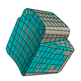
Figure 1 shows an example of a bottom-up meshed part. Although this part is relatively simple, it requires two regions and four bottom-up meshes to completely mesh the part. Abaqus/CAE displays bottom-up meshed regions using a mixture of the region geometry color (light tan) and the mesh color (light blue) to emphasize that the geometry and mesh may not be associated. Displaying both the geometry and the mesh allows you to view and edit the mesh-geometry associativity.