Creating and modifying prescribed conditions | |||||||||
|
| ||||||||
When you click Continue in the Create dialog box, you are prompted to select the region to which you want to apply the prescribed condition, unless the prescribed condition is applied to the whole model. You can apply connector loads and connector boundary conditions (displacement, velocity, and acceleration) only to wires that are associated with a connector section assignment. If you are select multiple wires, the connector sections assigned to the wires in the connector section assignments must have the available components of relative motion for which you are defining loads and boundary conditions. You can apply connector material flow boundary conditions only to endpoints of wires that are associated with a connector section assignment. Once you have selected the region, an editor appears in which you can specify additional information about the prescribed condition, such as its magnitude.
The top panel of each prescribed condition editor displays the name and type of the prescribed condition, the analysis step you are currently in, and the region of the model to which the prescribed condition will be applied. If you are editing a prescribed condition in the step in which it was first created, an Edit Region ( ) button appears next to the Region field; this button allows you to edit the region to which the prescribed condition is applied. If editing the region requires a complete redefinition of the prescribed condition (for example, if the prescribed condition is applied to the whole model or refers to subregions within the originally selected region), the Edit Region button does not appear. For more information, see Editing the region to which a prescribed condition is applied.
The format of the rest of the editor depends on the type of prescribed condition you are defining and on the step specified at the top of the editor. For example, the editor for concentrated forces is shown in Figure 1.
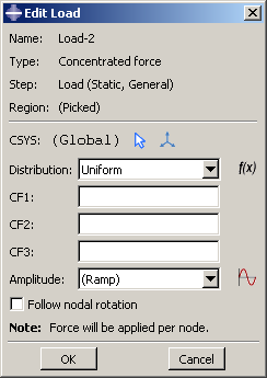
This editor contains special text fields in which you can specify the components of the force in the 1-, 2-, and 3-directions. The editor also contains an text field that allows you to vary the magnitude of the prescribed condition as a function of time. You can accept the default amplitude, select an amplitude that you have defined using the Amplitude toolset, or click  to define a new amplitude. (For more information, see The Amplitude toolset.”)
You can specify the coordinate system in which you will apply the following loads or boundary conditions:
- Loads
-
Concentrated force
Moment
General and shear surface traction
General shell edge load
Inertia relief
Current density
- Boundary conditions
-
Symmetry/antisymmetry/encastre
Displacement/rotation
Velocity/angular velocity
Acceleration/rotational acceleration
Eulerian mesh motion
Magnetic vector potential
All other prescribed conditions use the global coordinate system, with the exception of pressures, which are applied normal to the selected surfaces.
If the load or boundary condition allows you to specify the coordinate system, you can select an existing datum coordinate system or you can accept the global coordinate system. If the desired datum coordinate system does not exist, you can create it using the Datum toolset. (For more information, see Creating datum coordinate systems.) Alternatively, you can refer to an Abaqus/Standard user subroutine that defines the coordinate system (see ORIENT).
Note:
If you delete or suppress the datum coordinate system, the orientation of the load or boundary condition reverts to the global coordinate system.
The rules for creating and modifying predefined fields vary depending on the predefined field type:
Some predefined fields require that you specify only the initial conditions. You can create and edit this type of predefined field only in the initial step. Abaqus computes subsequent values for the predefined field as the analysis progresses. The predefined fields of this type are initial velocity specifications, hardening specifications, and material assignments (for Eulerian analyses). For more information, see Initial conditions in Abaqus/Standard and Abaqus/Explicit.
You can create predefined temperature fields for any step in the analysis. You can define the temperatures for the current model either by entering the values for the desired steps or by reading the temperature values computed by Abaqus in a previous analysis with thermal components. For more information, see “Temperature,” in Predefined Fields.
Note:
If you do not define initial values for a predefined field, that field is assumed to have a value of zero at the start of the analysis.
Once you have created a prescribed condition, you can modify the prescribed condition in the following ways:
You can modify some or all of the data that you entered in the editor when you created the prescribed condition.
You can use the managers to modify the stepwise history of the prescribed condition. (For more information, see What are step-dependent managers?.)
To display help on a particular manager or editor feature, select from the main menu bar and then click the feature of interest.