Connector section editors | |||||||
|
| ||||||
To create connector sections, select
from the main menu bar. A Create Connector Section dialog
box appears in which you can specify a name, category, and type for the
connector section that you want to create. When you select a connection type
from the Assembled/Complex or Basic
category, the available and constrained components of relative motion
(CORM) for that connection type are displayed
in the dialog box. In addition, you can click
 to see a schematic drawing of the connection type along with the
Abaqus
idealization of the connection. Once you have specified the name, category, and
type, click in the Create Connector
Section dialog box to display the connector section editor. For a
connection type in the MPC category, select the type and
enter data, if required. Click to finish creating the
MPC section and to close the Create Connector
Section dialog box.
to see a schematic drawing of the connection type along with the
Abaqus
idealization of the connection. Once you have specified the name, category, and
type, click in the Create Connector
Section dialog box to display the connector section editor. For a
connection type in the MPC category, select the type and
enter data, if required. Click to finish creating the
MPC section and to close the Create Connector
Section dialog box.
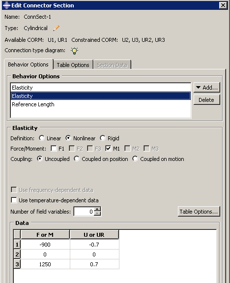
The connector section editor allows you to add the connector behaviors available in Abaqus/Standard and Abaqus/Explicit. When you click on the Behavior Options tabbed page, a list of behaviors appears. After you select a behavior, the name of the behavior appears in the Behavior Options list at the top of the editor, and the behavior becomes part of your connector section definition. The option definition area in the lower half of the editor changes to provide fields in which you can specify information for the currently selected behavior. If you want to remove a behavior from a connector section definition, you can select it from the Behavior Options list and then click .
Note:
Abaqus/CAE does not perform any checks for dependencies on other behaviors; you should ensure that all required behaviors are defined. For example, if you define a plasticity behavior, you must also define an elasticity behavior.
You can define multiple behaviors of the same type, such as elasticity. Only forces or moments that are consistent with the available components of relative motion for the chosen connection type can be selected to define behaviors. For example, the Behavior Options list in Figure 1 reflects that two behaviors and a behavior have been included in the connector section definition. The highlighted behavior defines elastic behavior in the same direction as the selected moment.
On the Table Options tabbed page, you can specify behavior settings for the regularization (Abaqus/Explicit analyses only) and the extrapolation of tabular data for all of the behavior options in a connector section. Alternatively, you can specify behavior settings for individual behavior options by clicking the button in the option definition area in the lower half of the editor. Behavior settings for individual behavior options take precedence over the connector section behavior settings.
When section data are applicable for the specified connection type, you can enter the data on the Section Data tabbed page.
You can display help on a particular feature of the editor by selecting from the main menu bar and then clicking the feature of interest. For detailed instructions on creating connector sections and defining behaviors and section data, see Creating connector sections, and Using the connector section editors.