An overview of composite layups | ||
| ||
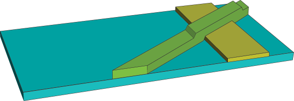
A ply represents a single piece of material that is placed in a mold during the composites manufacturing process. A composite layup can contain a different number of plies in different regions. For example, the composite layup in Figure 1 includes regions that contain a single ply, regions where two plies overlap, and a region where three plies overlap.
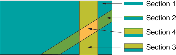
Figure 2 shows the same model that is depicted in Figure 1 but defined using composite shell sections. The number of plies cannot change within a composite shell section. Therefore, four composite shell sections, each with a constant number of plies, are required to define this simple model. Section 1 contains a single ply, sections 2 and 3 each contain two plies, and section 4 contains three plies.
Composite layups in Abaqus/CAE are designed to help you manage a large number of plies in a typical composite model. In contrast, composite sections are a product of finite element analysis and may be difficult to apply to a real-world application. Unless your model is relatively simple and all plies cover the same region, you will find it increasingly difficult to define your model using composite sections as you increase the number of plies. It can also be cumbersome to add new plies or remove or reposition existing plies.
The procedure for creating a composite layup with Abaqus/CAE mirrors the procedure for creating a real composite part—you start with a basic shape and then you add plies of different materials and thicknesses to selected regions and orient the plies to provide the greatest strength in a particular direction. The Abaqus/CAE composite layup editor allows you to easily add a ply, choose the region to which it is applied, specify its material properties, and define its orientation. You must specify ply names that are unique throughout the entire model to ensure the correct display of ply-based results. You can also read the definition of the plies in a layup from the data in a text file. This is convenient when the data are stored in a spreadsheet or were generated by a third-party tool. You can also suppress plies in your layup and experiment with the effect of adding and removing plies of different orientations.
It is important to specify the correct orientation of the fibers in a ply. Abaqus/CAE allows you to define a reference orientation for the layup as well as a reference orientation for each ply in the layup. In addition, you can specify the direction of the fibers in a ply relative to the reference orientation of the ply. By default, the coordinate system of a layup is the same as the coordinate system of the part; similarly, the coordinate system of a ply is the same as the coordinate system of the layup. Orientation definition is described in more detail in Understanding composite layups and orientations.
Using a composite layup to model a yacht hull, illustrates how you can analyze a complex three-dimensional model using the composite layup capability in Abaqus/CAE.