Understanding composite layups and orientations | ||
| ||
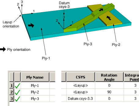
Composite layups in Abaqus/CAE make the process more manageable by deriving the orientation of the fibers from three parameters that are relative to each other—the layup orientation, the ply orientation, and an additional rotation—as shown in Figure 1.
- Layup orientation
-
The layup orientation defines the base or reference orientation of all the plies in the layup. In conventional and continuum shell layups, Abaqus projects the specified orientation onto the surface of the shell, aligning the direction of the layup orientation that you choose with the shell normal. In solid composite layups the orientation is not projected.
Abaqus/CAE provides several options for defining the layup orientation:
-
Part global: By default, the layup orientation is the same as the orientation of the part.
-
Coordinate system: You can create and select a datum coordinate system that defines the orientation.
-
Discrete orientation: You can create a discrete orientation that provides an orientation value for each mesh element to define the orientation.
-
Discrete field: You can create and select an orientation discrete field that defines a spatially varying orientation.
-
User-defined: You can define the orientation in user subroutine ORIENT. This option is valid only for Abaqus/Standard analyses.
-
Normal direction: For all options except User-defined, you can choose which axis defines the approximate normal direction of the composite layup.
-
Additional rotation: If you choose a Coordinate system, Discrete orientation, or Discrete field to define the layup orientation, you can specify an angle (in degrees) that defines an additional rotation about the specified normal direction for the entire layup. You can use a scalar discrete field to specify a spatially varying additional rotation angle.
-
- Ply orientation
-
The ply orientation defines the relative orientation of each ply. In conventional and continuum shell layups Abaqus projects the specified ply orientation onto the surface of the shell so that the ply normal direction is aligned with the shell normal and the layup stacking direction. In solid composite layups the plies are created with respect to the layup stacking direction, and the unprojected ply orientation defines the material orientation within a ply (see Figure 2).
Figure 2. Plies and ply orientations for shell and solid composite layups.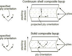
Abaqus/CAE calculates the ply orientation from a combination of two variables that you can specify—the coordinate system (CSYS) and a rotation angle about the normal direction.
In cases where Abaqus/CAE attempts to draw coordinate systems for ply orientations in composite layups at singularity points of the system (i.e., points for which the user-selected coordinate system and the geometric normal from either geometry or elements cannot be resolved into a valid orientation for display purposes in Abaqus/CAE), the coordinate system will be drawn collapsed.
If the layup orientation is specified using a discrete field, no display is available for either the layup or ply orientation. For continuum shell elements, Abaqus/CAE does not project the displayed orientations onto the midplane surface. In both of these cases, you can perform a data check and view the output database in the Visualization module to verify the orientations. For more information, see Performing a data check on a model.
- Coordinate system
-
Abaqus/CAE provides the following options for defining the coordinate system of the ply:
-
Layup: By default, the coordinate system of the ply is the same as the coordinate system of the layup.
-
CSYS: You can create and select a datum coordinate system that defines the coordinate system of the ply. If you choose to use a coordinate system for a ply, it overrides the layup orientation for that ply.
You can also select the axis of the coordinate system that defines the normal direction of the ply. The axis that you choose appears as the last digit in the CSYS column in the layup table. For example, Datum csys1.3 indicates that you chose Datum csys-1 to define the coordinate system of the ply, and you chose the 3-axis to define the normal.
-
- Rotation angle
-
The rotation angle defines the orientation of the fibers within each ply relative to the ply's coordinate system. For example, in a typical composite the fibers might be oriented at −45° or +90° relative to the coordinate system. You can also use a scalar discrete field to specify a fiber orientation that varies spatially across the ply. If you specify a rotation angle, the ply is rotated counterclockwise about the coordinate system normal, and the angle is measured relative to the 1-axis.
Figure 3 shows the orientation of four plies in a composite layup and the corresponding entries in the layup table.
Figure 3. Determining the orientation of each ply.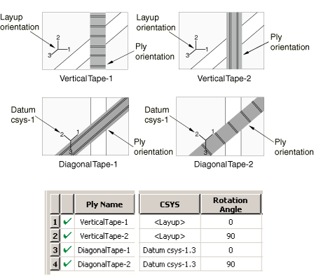
Abaqus/CAE determines the ply orientation as follows:
-
You selected the layup orientation to define the coordinate system of VerticalTape-1 and entered a rotation angle of 0°. The resulting ply orientation is along the 1-axis of the layup orientation.
-
You selected the layup orientation to define the coordinate system of VerticalTape-2 and entered a rotation angle of 90°. The resulting ply orientation is a rotation of 90° counterclockwise about the 3-axis (the normal direction) of the layup orientation. The rotation angle is measured relative to the 1-axis.
-
You selected Datum csys-1 to define the coordinate system of DiagonalTape-1 and entered a rotation angle of 0°. The resulting ply orientation is along the 1-axis of Datum csys-1.
-
You selected Datum csys-1 to define the coordinate system of DiagonalTape-2 and entered a rotation angle of 90°. The resulting ply orientation is a rotation of 90° counterclockwise about the 3-axis (the normal direction) of the datum coordinate system. The angle is measured relative to the 1-axis.