Using the volume fraction tool | ||
| ||
The discrete field that is created by the volume fraction tool can be used to assign material instances to the Eulerian part instance (see Assigning materials to Eulerian part instances). The topology of the assigned Eulerian material instance corresponds to the shape of the reference part instance within the Eulerian part instance.
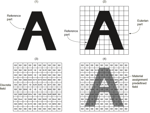
Figure 1 and the following procedure summarize the process of using the volume fraction tool:
-
Using any of the modeling tools and techniques in Abaqus/CAE, create a reference part that corresponds to the geometry of the desired Eulerian material region.
-
Instance the reference part within the Eulerian part instance. The reference part instance should spatially correspond to the desired Eulerian material region.
-
Use the volume fraction tool to create a discrete field based on a comparison of the reference part instance and the Eulerian part instance.
-
Define a material assignment predefined field for the Eulerian part instance using the discrete field created by the volume fraction tool.
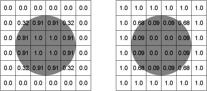
An option for the volume fraction tool controls whether the calculated discrete field represents the space inside the reference instance (the volume fraction is nonzero in elements that overlap the reference instance) or the space outside the reference instance (the volume fraction is nonzero in elements that do not overlap or partially overlap the reference instance), as depicted in Figure 2.
Typically, calculating the volume fraction outside of a reference instance is used to create an Eulerian material assignment around a Lagrangian part instance in a coupled Eulerian-Lagrangian analysis. Calculating the volume fraction inside of a reference instance is usually used to model complex material assignment fields within a pure Eulerian part instance; in this situation, the reference instance is suppressed after the Eulerian material is assigned. You can also calculate volume fractions inside of a reference instance to create an Eulerian material assignment on the inside of an enclosed Lagrangian shell in a coupled Eulerian-Lagrangian analysis.
To use the volume fraction tool, select from the main menu bar. For step-by-step instructions for using the tool, refer to Creating discrete fields for material volume fractions.
The Eulerian part instance that is used by the volume fraction tool must be the same instance to which materials are assigned. The Eulerian part must be meshed before using the volume fraction tool. You should not edit the part mesh after creating the discrete field, as the element numbering in the discrete field may not conform to the elements in the updated mesh.
The reference part instance used by the volume fraction tool can include unmeshed geometry, a native mesh, or orphan elements; deformable, Eulerian, and discrete rigid parts are all allowed. The volume fraction tool always uses the mesh representation (if available) of the reference part instance when calculating the discrete field; if the reference instance is partially meshed, only the meshed portion of the instance is considered in the volume fraction calculation. The mesh on the reference instance should be fine enough to capture all important geometric details in the subsequent material assignment.
The reference part instance must be either a three-dimensional solid or a fully enclosed three-dimensional shell. The faces of a shell enclosure must define a single, continuous surface; features that create T-intersections with the surface faces (such as ribs or interior dividing panels) are not allowed (see Figure 3). An Eulerian element is considered to be inside a shell reference instance if it lies within the volume enclosed by the shell surface.