What is a connector?

Connectors allow you to model mechanical relationships between two points in an assembly. The connection can be simple, such as a link, or the connection can impose more complicated constraints, such as constant velocity joints. The connector geometry is modeled using an assembly-level wire feature that contains one or more wires. The wires may connect two points in an assembly or connect a point to ground. You create a connector section that specifies the type of connection and connector behaviors, such as spring-like elasticity behavior. To complete the connector modeling, you create a connector section assignment that associates a connector section with the wires that you select and that specifies the orientations for the first and second points of the wires that you select. For more information on connectors, see About connectors.

For example, Figure 1 illustrates the crank mechanism that is used in the example problem Crank mechanism.

Figure 1. A crank mechanism modeled with connectors.

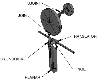
The model transmits a rotational motion through two universal joints and then converts the rotation into translational motion of two slides. An Abaqus Scripting Interface script that reproduces the crank mechanism model using Abaqus/CAE is provided with this example. The crank mechanism is modeled using nine part instances attached to each other through eight connectors modeled in Abaqus/CAE.