Creating the connector geometry, connector sections, and connector section assignments

You create the assembly-level wire features, connector sections, and connector section assignments in the Interaction module to model a connector. Abaqus/CAE provides two methods for modeling connectors: you can use the Connector Builder to perform all the steps involved in creating a single connector, including creation of the wire feature, connector section, connector section assignment, and any desired reference points and datum coordinate systems; or you can create multiple connectors by creating the wires, connector sections, and connector section assignments in separate dialog boxes in the Interaction module. If you choose the latter technique, you should create the desired reference points and datum coordinate systems before you begin modeling the connectors.

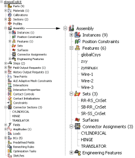
The Model Tree, shown in Figure 1, is helpful for understanding the organization of the reference points, datum coordinate systems, and wire features that you created in assembly-related modules, as well as connector sections and connector section assignments that you created in the Interaction module. You can use the Query toolset in the Interaction module to obtain connector assignment information for selected wires.

Figure 1. Wire features, connector sections, and connector section assignments in the Model Tree.

For detailed instructions, see the following sections: