Creating or modifying wire features for multiple connectors | |||||
|
| ||||
Context:
You can modify assembly-level wire features by selecting from the main menu bar. You select any wire from the feature that you want to modify and make changes in the Modify Wire Feature dialog box, as described in the procedure below. When you click in the dialog box, Abaqus/CAE does the following:
renames and suppresses the original wire feature;
creates a new wire feature using the same name as the original wire feature;
renames the geometry set that had contained the original wire feature, if it existed; and
if applicable, creates a new geometry set containing the modified wire feature.
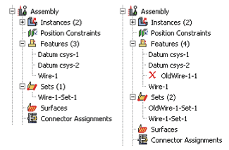
For example, Figure 1 shows that Wire-1 is renamed OldWire-1-1 and suppressed. Similarly, Wire-1-Set–1 is renamed OldWire-1-Set–1.
By using the default geometry set name created for a wire feature when you select wires to define connector section assignments, connector loads, and connector boundary conditions, you ensure that these objects remain valid if you modify the wire feature. Otherwise, objects that reference any part of the original wire feature are invalidated if you modify the wire feature; for example, if you define a connector force and select wires from the viewport or use a geometry set with a different name.
You can remove wires from the wire feature by selecting from the main menu bar. The operation to remove wire edges from the feature is stored as a feature of the part; therefore, you can use the Model Tree to delete or suppress the operation.
From the main menu bar in the Interaction module, select .
Tip: You can also modify an assembly-level wire feature using the  tool in the Interaction module toolbox.
In the Point Pairs portion of the dialog box, you can do the following:
-
To add more point pairs, specify the method, click
 , and select the points from the viewport. The representation of the added wire is highlighted in magenta.
 -
To edit a point, select the point in the table, click
 , and reselect a point. The selection highlighting in the viewport is updated to show the newly edited point.
 -
To identify a specific point pair in the viewport, select the desired row. The line connecting the selected point pair is highlighted in red.
-
To remove a point pair, select the desired row and click
 .
. -
To exchange the entries for Point 1 and Point 2 in a point pair, select the desired row and click
 .
.
-