FRIC | ||
| ||
ProductsAbaqus/Standard
User subroutine tested in a stress/displacement analysis
Elements tested
B31
Features tested
User subroutine to define frictional behavior for contact surfaces in a stress/displacement analysis.
Problem description
Abaqus provides a Coulomb friction model as the default behavior for frictional interfaces. In this test an alternative constitutive model is used. Here, the interface is assumed to have a viscoplastic behavior so that the slip strain rate is proportional to the shear stress. For this particular example
where k=0.001.
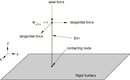
A fairly stiff beam element is used to model a rod. The contact between the bottom end of the rod and a three-dimensional rigid surface is modeled by specifying a master-slave contact pair. The bottom end of the rod constitutes the node-based slave surface, and the rigid surface represents the master surface. The rigid surface is kept fixed in space throughout the analysis and corresponds to the x–y plane. This configuration is shown in Figure 1. The rod, which is perpendicular to the rigid surface (that is, parallel to the z-axis), is forced into contact with the rigid surface and kept in compression by applying a concentrated load in the axial direction at the top of the rod. Subsequently, the rod is forced to slide around the surface by applying a concentrated load vector of the form
to the node at the top of the beam element. All rotations are constrained on this node as well.
The first two steps of the analysis set up an equilibrium solution in which the beam element is compressed by a force of 100. The rod is then slid in three steps (Steps 3–5), and each of the steps has a total time of unity. A tangential force of norm 100 is applied instantaneously during each of these steps to keep the norm of the shear stress vector constant. During these three steps the incremental slip vector and the interfacial shear stresses are checked for consistency with the assumed constitutive law.
Reference solution
- STEP 3:
A constant tangential force =100 and =0 is applied. The total slip at the end of this step is 0.1 along the x-axis since the applied shear stress is held constant with a value of 100 along this axis.
- STEP 4:
A constant tangential force ==70.71 is applied. The total slip at the end of this step is .17071 in the x-direction and .07071 in the y-direction since the applied shear stress is held constant with a value of 70.71 in each direction.
- STEP 5:
A constant tangential force =0 and =100 is applied. The total slip at the end of this step is .17071 in each direction since the applied shear stress is held constant with a value of 100 along the y-axis.
Results and discussion
The results match the analytical solution for Steps 3, 4, and 5.
Input files
- ufricxxx.inp
-
Stress/displacement analysis.
- ufricxxx.f
-
User subroutine FRIC used in ufricxxx.inp.
![]()
User subroutine tested in a coupled temperature-displacement analysis
Elements tested
C3D8T
Features tested
User subroutine to define frictional behavior for contact surfaces in a coupled temperature-displacement analysis.
Problem description
In this test the contact interface is assumed to have viscoplastic behavior so that the slip strain rate is proportional to the shear stress and average temperature of the interface. For this particular example
where 0.001 + 0.00001, and and represent the current temperature of the slave and master surface nodes, respectively.
Contact is defined between two solid blocks, A and B, as shown in Figure 2.
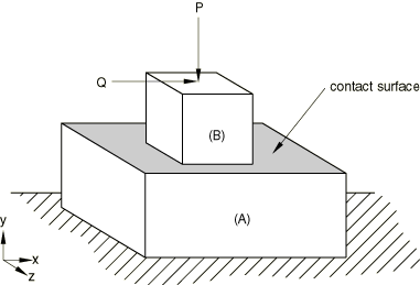
The base of block A is fixed in space. The analysis consists of a sequence of steps that are designed to verify the contact conditions and the frictional heat generated due to user-defined friction conditions. The material properties and the different boundary conditions and loads are chosen such that the analytical solution can be easily derived.
In Step 1 contact is established between blocks A and B.
In Step 2 contact between the two blocks is maintained by applying a downward force P=16000 on the top surface of block B. During these two steps the temperature of each block is kept at 0°.
Step 3 verifies that the friction law is applied correctly and that the proper amount of heat is generated due to friction. Block B is slid over block A by instantaneously applying a shear load Q of 100 in the x-direction. The temperature of block B is increased from 0° to 200° while maintaining the temperature of block A at 0°. During the sliding process the top surface of block A is fixed to keep the contact surfaces orthogonal to the y-axis. It is assumed that 50% of the frictional work is transformed into heat and that 50% of that heat goes through each contact surface. During this third step the incremental slip vector, the interfacial shear stresses, and the heat generated are checked for consistency with the assumed constitutive law.
Reference solution
At the end of the third step the total slip can be obtained by integrating the slip rate as
In Abaqus this integration is not carried out in a continuous fashion. It is carried out by discretizing the total time in given intervals, leading to the form
which results in a total slip of 0.155 if the unit time is divided into 10 equal intervals.
The heat generated by friction in each interval is
where =0.5 and =100. Half of this quantity goes through each contacting surface.
Results and discussion
Step 3 is carried out over a unit time period in 10 equal increments. As a result, a total slip of 0.155 is obtained. A value closer to 0.150 is obtained when the unit time is divided into more increments. The results obtained at the end of each increment in Step 3 also match the results obtained by analytically summing the slip over each time interval.
Input files
- ufricxxy.inp
-
Coupled temperature-displacement analysis.
- ufricxxy.f
-
User subroutine FRIC used in ufricxxy.inp.