Models for crushable foams | ||||||
|
| |||||
ProductsAbaqus/StandardAbaqus/Explicit
The volumetric hardening model is motivated by the experimental observation that foam structures usually experience a different response in compression and tension. In compression the ability of the material to deform volumetrically is enhanced by cell wall buckling processes as described by Gibson et al. (1982), Gibson and Ashby (1982), and Maiti et al. (1984). It is assumed that the foam cell deformation is not recoverable instantaneously and can, thus, be idealized as being plastic for short duration events. In tension, on the other hand, cell walls break readily; and as a result the tensile load bearing capacity of crushable foams may be considerably smaller than its compressive load bearing capacity. Under monotonic loading, the volumetric hardening model assumes perfectly plastic behavior for pure shear and negative hydrostatic pressure stress states, while hardening takes place for positive hydrostatic pressure stress states.
The isotropic hardening model was originally developed for metallic foams by Deshpande and Fleck (2000). It assumes symmetric behavior in tension and compression, and the evolution of the yield surface is governed by an equivalent plastic strain, which has contributions from both the volumetric plastic strain and the deviatoric plastic strain.
The mechanical behavior of crushable foams is known to be sensitive to the rate of straining. This effect can be introduced by a piecewise linear law or by the overstress power law model.
The strain rate decomposition
The volume change is decomposed as
where J is the ratio of current volume to original volume, is the elastic (recoverable) part of the ratio of current to original foam volume, and is the plastic (nonrecoverable) part of the ratio of current to original foam volume.
Volumetric strains are defined as
These definitions and Equation 1 result in the usual additive strain rate decomposition for volumetric strains:
The model also assumes the deviatoric strain rates decompose additively, so that the total strain rates decompose as
![]()
Elastic behavior
The elastic behavior can be modeled only as linear elastic
where represents the fourth-order elasticity tensor and and are the second-order stress and elastic strain tensors, respectively.
![]()
Plastic behavior
The yield surface and the flow potential for the crushable foam models are defined in terms of the pressure stress
and the Mises stress
The yield surface is defined as
and the flow potential is defined as
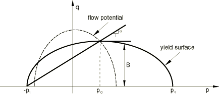
F and G can each be represented as an ellipse in the p–q stress plane with and representing the shape of the yield ellipse and the ellipse for the flow potential, respectively; is the center of the yield ellipse, and B is the length of the (vertical) q–axis of the yield ellipse. The flow potential is an ellipse centered in the origin. The yield surface and the flow potential are depicted in Figure 1.

The parameters and B of the yield ellipse (Equation 2) are related to the yield strength in hydrostatic compression, , and to the yield strength in hydrostatic tension, , by
where and are positive quantities and A is the length of the (horizontal) p-axis of the yield ellipse.
The shape factor, , remains as a constant during any plastic deformation process. The evolution of the yield ellipse is controlled by a plastic strain measure, , which is the volumetric compacting plastic strain, , for the volumetric hardening model, and the equivalent plastic strain, (to be defined later), for the isotropic hardening model.
To define the hardening behavior, uniaxial compression test data are required. A piecewise linear hardening curve of uniaxial Cauchy stress versus axial (logarithmic) plastic strain must be entered in a tabular form.
![]()
Crushable foam model with volumetric hardening
The volumetric hardening model assumes that the hydrostatic tension strength, , remains constant throughout any plastic deformation process. By contrast, the hydrostatic compression strength evolves as a result of compaction (increase in density) or dilation (reduction in density) of the material:
Yield surface
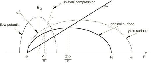
The yield surface for the crushable foam model, depicted in Figure 2,

is defined by
where the parameter represents the shape of the yield ellipse in the p–q stress plane and can be calculated from the initial yield strength in uniaxial compression, , taken as a positive value; the initial yield strength in hydrostatic compression, ; and the yield strength in hydrostatic tension, ; as
where the yield stress ratios, and , are provided by the user and can be functions of temperature and other field variables. For a valid yield surface the choice of yield stress ratios must be such that and . The yield surface is the Mises circle in the deviatoric stress plane.
Flow potential
The plastic strain rate for the volumetric hardening model is assumed to be
where is the equivalent plastic strain rate defined as
and G is the flow potential, chosen in this model as
This potential is a particular case of Equation 3 with . A geometrical representation of the flow potential in the p–q stress plane is shown in Figure 2.
Equation 4 gives a direction of flow that is identical to the stress direction for radial paths. This is motivated by simple laboratory experiments performed by Bilkhu (1987), which suggest that loading in any principal direction causes insignificant deformation in the other directions. As a result, the plastic flow is nonassociative. Therefore, the use of this foam model generally requires the solution of nonsymmetric equations.
Hardening
The yield surface intersects the p-axis at and . We assume that remains fixed throughout any plastic deformation process. By contrast, the compressive strength, , evolves as a result of compaction (increase in density) or dilation (reduction in density) of the material. The evolution of the yield surface can be expressed through the evolution of the yield surface size on the hydrostatic stress axis, , as a function of the value of volumetric compacting plastic strain, . With constant, this relation can be obtained from a user-provided uniaxial compression test data using
along with the fact that in uniaxial compression (due to zero plastic Poisson's ratio). Thus, the user provides input to the hardening law by only specifying, in the usual tabular form, the value of the yield stress in uniaxial compression as a function of the absolute value of the axial plastic strain. The table must start with a zero plastic strain (corresponding to the virgin state of the material), and the tabular entries must be given in ascending magnitude of . If desired, the yield stress can also be a function of temperature and other predefined field variables.
![]()
Crushable foam model with isotropic hardening
The isotropic hardening model was originally developed for metallic foams by Deshpande and Fleck (2000). The model assumes similar behaviors in tension and compression. The yield surface is an ellipse centered at the origin in the p–q stress plane and evolves in a self-similar manner governed by the equivalent plastic strain.
Yield surface
The yield surface for the isotropic hardening model is defined as
with
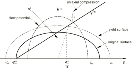
where represents the shape of the yield ellipse in the p–q stress plane, B defines the size of the yield ellipse, is the yield strength in hydrostatic compression, and is the absolute value of the yield strength in uniaxial compression. The yield surface is the Mises circle in the deviatoric stress plane, and an ellipse in the meridional plane as depicted in Figure 3.

The parameter can be calculated using the initial yield stress in uniaxial compression, , and the initial yield stress in hydrostatic compression, , as
The strength ratio k is provided by the user and must be in the range of 0 and 3. For many low-density foams the initial yield surface is close to a circle in the p–q stress plane, which indicates that the value of is approximately one. The special case of corresponds to the Mises yield surface.
Flow potential
The flow potential for the isotropic hardening model is chosen as
where represents the shape of the flow potential in the p–q stress plane and is related to the plastic Poisson's ratio, , by
The plastic Poisson's ratio, which is the ratio of the transverse to the longitudinal plastic strain under uniaxial compression, should be defined by the user; and it must be in the range of −1 and 0.5. The upper limit, , corresponds to an incompressible plastic flow.
The plastic strains are defined to be normal to a family of self-similar flow potentials parametrized by the value of the potential G
where is the nonnegative plastic flow multiplier. The hardening of the foam is described through , where is the equivalent plastic strain. The evolution of is assumed to be governed by the equivalent plastic work expression; i.e.,
The equivalent plastic strain is equal to the absolute value of the axial plastic strain in uniaxial tension or compression.
The plastic flow is associative when the value of is the same as that of . In general, the plastic flow is nonassociated to allow for the independent calibrations of the shape of the yield surface and the plastic Poisson's ratio. For many low-density foams the plastic Poisson's ratio is nearly zero, which corresponds to a value of .
Hardening
A simple uniaxial compression test is sufficient to define the evolution of the yield surface. The hardening law defines the value of the yield stress in uniaxial compression as a function of the absolute value of the axial plastic strain. The piecewise linear relationship is entered in tabular form. The table must start with a zero plastic strain (corresponding to the virgin state of the materials) and must be given in ascending magnitude of . If desired, the yield stress can also be a function of temperature and other predefined field variables.