*SYMMETRIC MODEL GENERATION | ||||||
|
| |||||
ProductsAbaqus/Standard
TypeModel data
LevelThis option is not supported in a model defined in terms of an assembly of part instances.
Required, mutually exclusive parameters
- PERIODIC
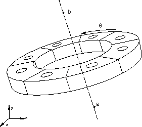
Use this parameter to indicate that a periodic three-dimensional model must be generated by revolving a single three-dimensional sector of the model about the symmetry axis (see Figure 1).
Set PERIODIC=CONSTANT (default) to indicate that each generated sector in the periodic model has a constant angle.
Set PERIODIC=VARIABLE to indicate that each generated sector in the periodic model can have a variable angle in the circumferential direction.
In both cases each sector always has the same geometry and mesh. The surfaces on both sides of the original sector must be completely planar when PERIODIC=VARIABLE. If the surface meshes on either side of the original sector are not matched completely, constraints between the neighboring pairs of corresponding surfaces specified on the data lines will be applied with an automatically generated TIE option when the periodic three-dimensional model is generated.
- REFLECT
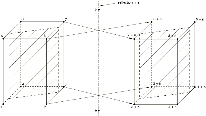
Set REFLECT=LINE to indicate that a three-dimensional model must be generated by reflecting a partial three-dimensional model through a symmetry line (Figure 3).
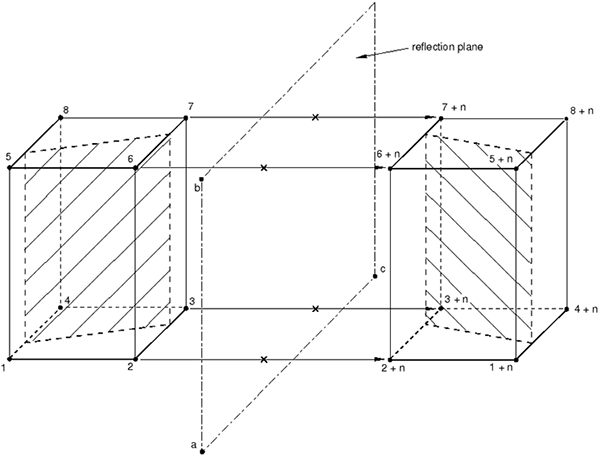
Set REFLECT=PLANE to indicate that a three-dimensional model must be generated by reflecting a partial three-dimensional model through a symmetry plane (Figure 4).
- REVOLVE
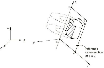
Include this parameter to indicate that a three-dimensional model must be generated by revolving the cross-section of an axisymmetric mesh about the symmetry axis. See Figure 2.
![]()
Optional parameters
- ELEMENT OFFSET
Set this parameter equal to an integer to define the offset for element numbering. When the REVOLVE parameter is used, the offset is added to each element number on the previous cross-section to obtain the numbering of the elements on the next cross-section, starting at the reference cross-section, . The reference cross-section uses the same numbering as the original axisymmetric model. When the REFLECT parameter is used, the offset is added to the original element numbers to define the numbering on the reflected part. The default and minimum value is the largest element number used in the original model.
- FILE NAME
Set this parameter equal to the name of an external file (without an extension) to which keyword and data lines for the model definition will be written. The extension .axi will be added to the file name provided by the user. See Input Syntax Rules for the syntax of such file names.
- NODE OFFSET
Set this parameter equal to an integer to define the offset used for node numbering. When the REVOLVE parameter is used, the offset is added to each node number on the previous cross-section to obtain the numbering of the nodes on the next cross-section, starting at the reference cross-section, . The reference cross-section uses the same numbering as the original axisymmetric model. When the REFLECT parameter is used, the offset is added to the original node numbers to define the numbering on the reflected part. The default and minimum value is the largest node number used in the original model.
- TOLERANCE
Set this parameter equal to the distance to be used in the search for duplicate nodes. Duplicate nodes on the axis of revolution of a revolved model, on the connection planes between sectors of a periodic model, and on the connection plane between the two parts of a reflected model will be eliminated. The default distance is 1.0% of the average element dimension.
![]()
Data lines if each generated sector in the periodic model has a constant angle (PERIODIC=CONSTANT)
- First line
X-coordinate of point a.
Y-coordinate of point a.
Z-coordinate of point a.
X-coordinate of point b.
Y-coordinate of point b.
Z-coordinate of point b.
- Second line
Segment angle, (in degrees), of the original three-dimensional sector. .
Number of three-dimensional repetitive sectors, including the original sector in the generated periodic model. The default is 1.
- Third line (needed if the surface meshes on either side of the original sector are not matched completely)
The surface name on one side of the original sector.
The corresponding surface name on the other side of the original sector, measured at a positive angle, , around the revolving axis.
Tolerance distance within which nodes on one surface of a sector must lie from the corresponding surface of the neighboring sector to be constrained. Nodes on the surface of the sector that are further away from the corresponding surface of the neighboring sector than this distance are not constrained. The default value for this tolerance distance is 5% or 10% of the typical element size in the surfaces of the original sector, depending on whether node-to-surface or surface-to-surface type of constraints are used, respectively.
Include the “word” SURFACE (default) to generate a surface-to-surface type of constraint or the “word” NODE to generate a node-to-surface type of constraint.
Repeat the third data line as often as necessary to define pairs of corresponding surfaces on each side of the original repetitive sector. Constraints between the neighboring pairs of corresponding surfaces will be applied with an automatically generated TIE option when the periodic three-dimensional model is generated.
![]()
Data lines if each generated sector in the periodic model has a variable angle (PERIODIC=VARIABLE)
- First line
X-coordinate of point a.
Y-coordinate of point a.
Z-coordinate of point a.
X-coordinate of point b.
Y-coordinate of point b.
Z-coordinate of point b.
- Second line
Segment angle, (in degrees), of the original three-dimensional sector. .
Number of three-dimensional sectors that have the same angle as the original sector to be generated, including the original sector. The default is 1.
- Third line
Number of additional three-dimensional sectors to be generated.
Angular scaling factor in the circumferential direction with respect to the original sector. The default is 1.0.
Repeat the third data line as often as necessary to define all the sectors of the model in the circumferential direction.
- Subsequent lines (needed if the surface meshes on either side of the original sector are not matched completely)
The surface name on one side of the original sector.
The corresponding surface name on the other side of the original sector, measured at a positive angle, , around the revolving axis.
Tolerance distance within which nodes on one surface of a sector must lie from the corresponding surface of the neighboring sector to be constrained. Nodes on the surface of the sector that are further away from the corresponding surface of the neighboring sector than this distance are not constrained. The default value for this tolerance distance is 5% or 10% of the typical element size in the surfaces of the original sector, depending on whether node-to-surface or surface-to-surface type of constraints are used, respectively.
Include the “word” SURFACE (default) to generate a surface-to-surface type of constraint or the “word” NODE to generate a node-to-surface type of constraint.
Repeat the subsequent data line as often as necessary to define more pairs of corresponding surfaces on each side of the original sector. Constraints between the neighboring pairs of corresponding surfaces will be applied with the automatically generated TIE option when the periodic three-dimensional model is generated.
![]()
Data line if REFLECT=LINE
- First (and only) line
X-coordinate of point a.
Y-coordinate of point a.
Z-coordinate of point a.
X-coordinate of point b.
Y-coordinate of point b.
Z-coordinate of point b.
![]()
Data lines if REFLECT=PLANE
- First line
X-coordinate of point a.
Y-coordinate of point a.
Z-coordinate of point a.
X-coordinate of point b.
Y-coordinate of point b.
Z-coordinate of point b.
- Second line
X-coordinate of point c.
Y-coordinate of point c.
Z-coordinate of point c.
![]()
Data lines if the REVOLVE parameter is included
- First line
X-coordinate of point a.
Y-coordinate of point a.
Z-coordinate of point a.
X-coordinate of point b.
Y-coordinate of point b.
Z-coordinate of point b.
- Second line
X-coordinate of point c.
Y-coordinate of point c.
Z-coordinate of point c.
- Third line
Segment angle, , through which the cross-section must be revolved. . The segments are connected, so, except for the first segment, each segment starts at the end point of the segment given on the previous data line.
Number of subdivisions or elements to be used in the segment. The default is 1. A single element subdivision must not exceed 45° when general elements are used or 180° when cylindrical elements are used.
Bias ratio to be used in the spacing of nodes generated over the segment. The value is set to the ratio of adjacent angles between nodes along each arc of nodes generated. Thus, if the value is less than one, the nodes are concentrated toward the beginning of the segment; and if the value is greater than one, the nodes are concentrated toward the end of the segment. The default is 1.0.
Include the “word” GENERAL (default) to generate general three-dimensional elements or the “word” CYLINDRICAL to generate cylindrical elements.
Repeat the third data line as often as necessary to define the discretization of the model in the circumferential direction.