ProductsAbaqus/StandardAbaqus/ExplicitAbaqus/CAE
TypeModel data in Abaqus/Standard; Model or history data in Abaqus/Explicit
LevelModel in Abaqus/Standard; Model or Step in Abaqus/Explicit
Abaqus/CAEInteraction module
Required parameters
- PROPERTY
-
Use this parameter to specify the property type being assigned. To modify more than one type of surface property, include the SURFACE PROPERTY ASSIGNMENT option more than once with different values for this parameter.
Set PROPERTY=BEAM SMOOTHING to control smoothing of beam segments in beam-to-beam contact. This parameter value applies only to Abaqus/Standard analyses.
Set PROPERTY=CRUSH TRIGGER to control crush initiation of a crushable surface. This parameter value applies only to Abaqus/Explicit analyses.
Set PROPERTY=FEATURE EDGE CRITERIA to control which primary feature edges and secondary feature edges should be activated in the general contact domain.
Set PROPERTY=GEOMETRIC CORRECTION to assign geometric corrections.
Set PROPERTY=OFFSET FRACTION to assign the surface offset as a fraction of the surface thickness.
Set PROPERTY=ORIENTATION to assign a coordinate system for local tangent directions to the surface and/or specify preferential frictional directions to the surface in the context of surface-based anisotropic friction. This parameter value applies only to Abaqus/Explicit analyses.
Set PROPERTY=THICKNESS to assign the surface thickness.
Set PROPERTY=VERTEX CRITERIA to control which nodes of feature edges should be considered vertex nodes in the general contact domain. This parameter value applies only to Abaqus/Standard analyses.
![]()
Optional parameters
- DEFINITION
-
This parameter is relevant only for surface properties defined using PROPERTY=GEOMETRIC CORRECTION.
Set DEFINITION=COORDINATES (default) to define the parameters for the geometry correction by giving the coordinates of one or more points, depending on the surface shape.
Set DEFINITION=NODES to define the parameters for the geometry correction by giving the global number of one or more nodes, depending on the surface shape.
- FRICTION ANISOTROPY
-
This parameter applies only to Abaqus/Explicit analyses with PROPERTY=ORIENTATION.
Set FRICTION ANISOTROPY=EPSILON (default) to define the frictional directional preference factor on the data lines.
Set FRICTION ANISOTROPY=RATIO to define the ratio r on the data lines.
![]()
Data lines for PROPERTY=BEAM SMOOTHING
- First line
-
Surface name.
-
A scalar value between 0.0 and 0.5 (0.2 is the default).
Repeat this data line as often as necessary. If the beam smoothing assignments overlap, the last assignment applies in the overlap region.
-
![]()
Data lines for PROPERTY=CRUSH TRIGGER in Abaqus/Explicit
- First line
-
-
Surface name.
-
Specify TRIGGER (default), NO TRIGGER, or NO CRUSH. If NO TRIGGER or NO CRUSH is specified, no further entries are needed.
-
If TRIGGER (default) is specified, a scalar value representing the stress required to initiate crushable behavior as a factor of the crush stress (CRUSH STRESS) defined on the material associated with the surface.
Repeat this data line as often as necessary. If the feature edge criteria assignments overlap, the last assignment applies in the overlap region.
-
![]()
Data lines for PROPERTY=FEATURE EDGE CRITERIA in Abaqus/Standard
- First line
-
-
Surface name. If the surface name is omitted, a default surface that encompasses the entire general contact domain is assumed.
-
A scalar value between 0° and 180° representing the cutoff feature angle (in degrees), PERIMETER EDGES, or NO FEATURE EDGES. The default is 45°. This field activates edges to participate in edge-to-surface contact.
-
This field is intentionally left blank and is unused.
-
A scalar value between 0° and 180° representing the cutoff feature angle (in degrees), PERIMETER EDGES, or NO FEATURE EDGES. The entry on this field activates edges to participate in edge-to-edge contact. The default is NO FEATURE EDGES.
Repeat this data line as often as necessary. If the feature edge criteria assignments overlap, the last assignment applies in the overlap region.
-
![]()
Data lines for PROPERTY=FEATURE EDGE CRITERIA in Abaqus/Explicit
- First line
-
-
Surface name. A non-blank surface name is required if the ALL EDGES or PICKED EDGES options are specified. If the surface name is omitted when using the PERIMETER EDGES, NO FEATURE EDGES, or cutoff feature angle options, a default surface that encompasses the entire general contact domain is assumed.
-
The criterion for primary feature edges. PERIMETER EDGES (default), ALL EDGES, PICKED EDGES, NO FEATURE EDGES, or a scalar value representing the cutoff feature angle (in degrees).
-
The criterion for secondary feature edges. ALL REMAINING EDGES, PERIMETER EDGES, PICKED EDGES, or a scalar value representing the cutoff feature angle (in degrees).
Repeat this data line as often as necessary. If the feature edge criteria assignments overlap, the last assignment applies in the overlap region.
-
![]()
Data lines for PROPERTY=GEOMETRIC CORRECTION, DEFINITION=COORDINATES to define smoothing on regions of surfaces
- First line
-
-
Surface name.
-
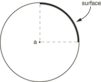
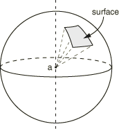
Specify CIRCUMFERENTIAL, SPHERICAL, TOROIDAL, NONE, or leave blank. If NONE or blank is specified, no further entries are required.
-
Global X-coordinate of point a (see Figure 1 through Figure 4, depending on surface shape).
-
Global Y-coordinate of point a.
-
Global Z-coordinate of point a (only for three-dimensional).
-
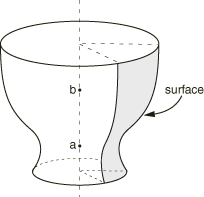
Global X-coordinate of point b (only for three-dimensional circumferential or toroidal; see Figure 2 or Figure 4, depending on surface shape).
-
Global Y-coordinate of point b (only for three-dimensional circumferential or toroidal).
-
Global Z-coordinate of point b (only for three-dimensional circumferential or toroidal).
-
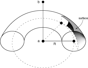
Distance R (only for three-dimensional toroidal; see Figure 4).
Repeat this data line as often as necessary. If the geometry correction assignments overlap, the last assignment applies in the overlap region. For toroidal shapes the line joining point a and the center of the circular arc should be perpendicular to the axis of revolution.
-
![]()
Data lines for PROPERTY=GEOMETRIC CORRECTION, DEFINITION=NODES to define smoothing on regions of surfaces
- First line
-
-
Surface name.
-
Specify CIRCUMFERENTIAL, SPHERICAL, TOROIDAL, NONE, or leave blank. If NONE or blank is specified, no further entries are required.
-
Node number of the node at point a (see Figure 1 through Figure 4, depending on surface shape).
-
Node number of the node at point b (only for three-dimensional circumferential or toroidal; see Figure 2 or Figure 4, depending on surface shape).
-
Distance R (only for three-dimensional toroidal; see Figure 4).
Repeat this data line as often as necessary. If the geometry correction assignments overlap, the last assignment applies in the overlap region. For toroidal shapes the line joining point a and the center of the circular arc should be perpendicular to the axis of revolution.
-
![]()
Data lines for PROPERTY=OFFSET FRACTION
- First line
-
Surface name. If the surface name is omitted, a default surface that encompasses the entire general contact domain is assumed. Faces specified on elements other than shell elements, membrane elements, rigid elements, and surface elements will be ignored.
-
ORIGINAL (default), SPOS, SNEG, or a value between –0.5 and 0.5. The offset defines the distance (as a fraction of the thickness) from the midsurface to the reference surface (containing the nodes of the element). Positive values of the offset are in the positive element normal direction. The default is ORIGINAL, which indicates that the offset specified in element section definitions (via the OFFSET parameter on SHELL SECTION or RIGID BODY) will be used.
Repeat this data line as often as necessary. If the offset fraction assignments overlap, the last assignment applies in the overlap region.
-
![]()
Data lines for PROPERTY=ORIENTATION
- First line
- Surface name.
- A valid orientation system name. If the orientation system name is omitted or the surface is an analytic rigid one, a default orientation is used.
- Scalar value of the extra rotation (in degrees) applied to the orientation system once it has been projected to the surface. The default value is 0.
- Scalar value of the frictional directional preference factor (within the range –1.0 to 1.0, default 0.0) or the friction coefficients ratio r (greater than 0.0, default 1.0) depending on the value of the FRICTION ANISOTROPY parameter.
Repeat this data line as often as necessary. If the directional preference assignments overlap, the last assignment applies in the overlap region.
![]()
Data lines for PROPERTY=THICKNESS
- First line
-
Surface name. If the surface name is omitted, a default surface that encompasses the entire general contact domain is assumed.
-
ORIGINAL (default), THINNING (available only in Abaqus/Explicit), or a scalar value representing a nominal thickness.
-
A constant scaling factor (default is 1.0).
Repeat this data line as often as necessary. If the thickness assignments overlap, the last assignment applies in the overlap region.
-
![]()
Data lines for PROPERTY=VERTEX CRITERIA in Abaqus/Standard
- First line
-
-
Surface name. If the surface name is omitted, a default surface that encompasses the entire general contact domain is assumed.
-
ALL VERTICES, NO VERTICES, or a scalar value between 10° and 90° representing the vertex angle threshold (in degrees). The default is 20°. This field activates vertex nodes to participate in vertex-to-surface contact.
Repeat this data line as often as necessary. If the vertex criteria assignments overlap, the last assignment applies in the overlap region.
-