ProductsAbaqus/StandardAbaqus/Explicit
TypeModel data
LevelPartPart instance
Required parameters
- ELEMENT
-
Set ELEMENT=BEAM to define rebar in beam elements in an Abaqus/Standard analysis.
Set ELEMENT=SHELL to define rebar in three-dimensional shell elements. Rebar cannot be used with triangular shell elements.
Set ELEMENT=AXISHELL to define rebar in axisymmetric shell elements.
Set ELEMENT=MEMBRANE to define rebar in three-dimensional membrane elements. Rebar cannot be used with triangular membrane elements.
Set ELEMENT=AXIMEMBRANE to define rebar in axisymmetric membrane elements in an Abaqus/Standard analysis.
Set ELEMENT=CONTINUUM to define rebar in continuum (solid) elements. Rebar cannot be used with any plane triangular, triangular prism, tetrahedral, or infinite elements.
- MATERIAL
-
Set this parameter equal to the name of the material of which these rebar are made.
- NAME
-
Set this parameter equal to a label that will be used to refer to this rebar set. This label can be used in defining rebar prestress and output requests. Each layer of rebar must be assigned a separate name in a particular element or element set.
![]()
Optional parameters
- GEOMETRY
-
This parameter is not meaningful for rebar in beams, axisymmetric shells, or axisymmetric membranes, or for single rebar in continuum elements.
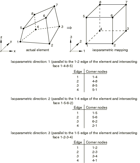
Set GEOMETRY=ISOPARAMETRIC (default) to indicate that the layer of rebar is parallel to a direction of the element local (isoparametric) coordinate system.
Set GEOMETRY=SKEW to indicate that the rebar layer is in a skew direction with respect to the element faces.
- ISODIRECTION
-
Set this parameter equal to the isoparametric direction from which the rebar angle output will be measured. The default is 1.
- ORIENTATION
-
This parameter is meaningful only for skew rebar in shell and membrane elements. Set this parameter equal to the name of an orientation definition that defines the angular orientation of the rebar. This parameter is not permitted with axisymmetric shell and axisymmetric membrane elements.
- SINGLE
-
This parameter is meaningful only for continuum elements. Include this parameter if a single rebar is being defined by each data line. If this parameter is omitted, each line defines a layer of uniformly spaced rebar in the element isoparametric space.
![]()
Data lines to define rebar in beam elements
- First line
Element number or name of the element set that contains these rebar.
Cross-sectional area of the rebar.
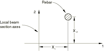
Distance (see Figure 1).
Distance .
Repeat this data line as often as necessary. Each line defines a single rebar.
![]()
Data lines to define isoparametric rebar in three-dimensional shell elements
- First line
Element number or name of the element set that contains these rebar.
Cross-sectional area of each rebar.
Spacing of the rebar in the plane of the shell. The default is 1.0.
Position of the rebar in the shell section thickness direction. This value is given as the distance of the rebar from the middle surface of the shell, positive in the direction of the positive normal to the shell. This value is modified if the NODAL THICKNESS parameter is included with the SHELL SECTION option of the underlying shell element.
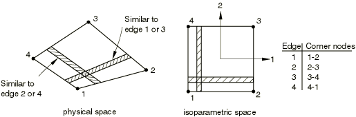
Edge number to which the rebar are parallel in the element's local (isoparametric) coordinate system. See Figure 2.
Repeat this data line as often as necessary. Each line defines a layer of rebar.
![]()
Data lines to define isoparametric rebar in three-dimensional membrane elements
- First line
Element number or name of the element set that contains these rebar.
Cross-sectional area of each rebar.
Spacing of the rebar in the plane of the membrane. The default is 1.0.
Edge number to which the rebar are parallel in the element's local (isoparametric) coordinate system. See Figure 2.
Repeat this data line as often as necessary. Each line defines a layer of rebar.
![]()
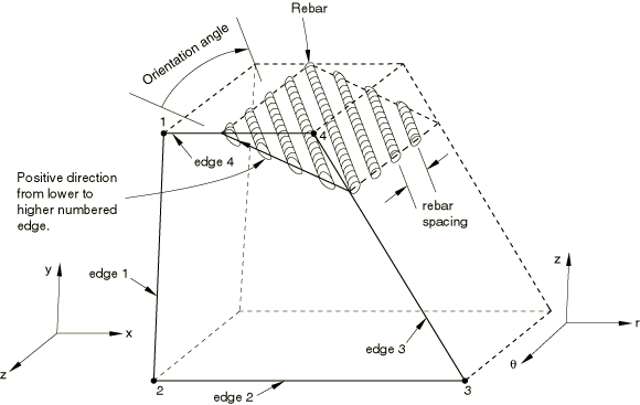
Data lines to define skew rebar in three-dimensional shell elements
- First line
Element number or name of the element set that contains these rebar.
Cross-sectional area of each rebar.
Spacing of rebar in the plane of the shell. The default is 1.0.
Position of the rebar in the shell section thickness direction. This value is given as the distance of the rebar from the middle surface of the shell, positive in the direction of the positive normal to the shell. This value is modified if the NODAL THICKNESS parameter is included with the SHELL SECTION option of the underlying shell element.
Angular orientation of rebar (in degrees) between the positive local 1-direction and the rebar. The optional ORIENTATION parameter given on the SHELL SECTION option should have no influence on the rebar angular orientation.
Repeat this data line as often as necessary. Each line defines a layer of rebar.
![]()
Data lines to define skew rebar in three-dimensional membrane elements
- First line
Element number or name of the element set that contains these rebar.
Cross-sectional area of each rebar.
Spacing of rebar in the plane of the membrane. The default is 1.0.
Angular orientation of rebar (in degrees) between the positive local 1-direction and the rebar. The optional ORIENTATION parameter given on the MEMBRANE SECTION option should have no influence on the rebar angular orientation.
Repeat this data line as often as necessary. Each line defines a layer of rebar.
![]()
Data lines to define rebar in axisymmetric shell elements
- First line
Element number or name of the element set that contains these rebar.
Cross-sectional area of each rebar.
Spacing of rebar in this rebar layer. The default is 1.0.
Position of the rebar in the shell section thickness direction. This value is given as the distance of the rebar from the middle surface of the shell, positive in the direction of the positive normal to the shell. This value is modified if the NODAL THICKNESS parameter is included with the SHELL SECTION option of the underlying shell element.
Angular orientation of rebar from the meridional plane in degrees (0° is meridional, 90° is circumferential). Positive rotation is about the positive normal to the shell.
Radial position at which the spacing of the rebar is measured. If this entry is nonzero, it is assumed that the rebar spacing varies linearly with radial position. If this entry is zero or blank, the rebar spacing does not vary with position. This entry has no meaning for circumferential rebar.
Repeat this data line as often as necessary. Each line defines a layer of rebar.
![]()
Data lines to define rebar in axisymmetric membrane elements
- First line
Element number or name of the element set that contains these rebar.
Cross-sectional area of each rebar.
Spacing of rebar in this rebar layer. The default is 1.0.
Angular orientation of rebar from the meridional plane in degrees (0° is meridional, 90° is circumferential). Positive rotation is about the positive normal to the membrane.
Radial position at which the spacing of the rebar is measured. If this entry is nonzero, it is assumed that the rebar spacing varies linearly with radial position. If this entry is zero or blank, the rebar spacing does not vary with position. This entry has no meaning for circumferential rebar.
Repeat this data line as often as necessary. Each line defines a layer of rebar.
![]()
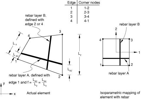
Data lines to define a layer of uniformly spaced rebar in continuum elements (SINGLE parameter omitted) when the layer is parallel to two isoparametric directions in the element's local (isoparametric) coordinate system (GEOMETRY=ISOPARAMETRIC)
- First line
Element number or name of the element set that contains these rebar.
Cross-sectional area of each rebar.
Spacing of rebar. The default is 1.0.
Orientation of rebar in degrees. See Figure 3.
Fractional distance from the edge given below, f (ratio of the distance between the edge and the rebar to the distance across the element).
Edge number from which the rebar are defined. See Figure 4 or Figure 7.
Isoparametric direction (for three-dimensional elements only).
For axisymmetric elements only, the radial position at which the spacing of the rebar is measured. If this entry is nonzero, the rebar spacing is assumed to vary linearly with radial position. If this entry is zero or blank, the rebar spacing does not vary with position.
Repeat this data line as often as necessary. Each line defines a layer of rebar.
![]()
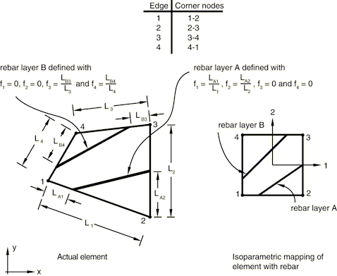
Data lines to define a layer of uniformly spaced rebar in continuum elements (SINGLE parameter omitted) when the layer is parallel to only one isoparametric direction in the element's local (isoparametric) coordinate system (GEOMETRY=SKEW)
- First line
Element number or name of the element set that contains these rebar.
Cross-sectional area of each rebar.
Spacing of rebar. The default is 1.0.
Orientation of rebar in degrees. See Figure 3.
For axisymmetric elements only, give the radial position at which the spacing of the rebar is measured. If this entry is nonzero, the rebar spacing is assumed to vary linearly with radial position. If this entry is zero or blank, the rebar spacing does not vary with position.
Isoparametric direction (for three-dimensional elements only).
- Second line
Fractional distance along edge 1, (see Figure 5).
Fractional distance along edge 2, .
Fractional distance along edge 3, .
Fractional distance along edge 4, .
Only the two values corresponding to the two edges that the rebar intersects can be nonzero.
Repeat the first and second data lines as often as necessary. Each pair of lines defines a layer of rebar.
![]()
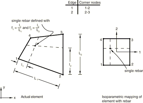
Data lines to define a single rebar in continuum elements (SINGLE parameter included)
- First line
Element number or name of the element set that contains the rebar.
Cross-sectional area of the rebar.
Fractional distance, , locating the rebar's position in the element (see Figure 6).
Fractional distance, , locating the rebar's position in the element.
Isoparametric direction (for three-dimensional elements only).
In three-dimensional cases the fractional distances , and are given along the first two edges of the face identified in Figure 7 for the isoparametric direction chosen.
Repeat this data line as often as necessary. Each line defines a single rebar.