*NCOPY | ||||||
|
| |||||
ProductsAbaqus/StandardAbaqus/ExplicitAbaqus/CAE
TypeModel data
LevelPartPart instance
Abaqus/CAENot applicable; copying portions of sketches and instancing of parts serve similar purposes.
Required parameters
- CHANGE NUMBER
-
Set this parameter equal to an integer that will be added to each of the existing node numbers to define the node numbers of the nodes being created.
- OLD SET
-
Set this parameter equal to the name of the node set being copied. This set will be used for the copy operation with the nodes that belong to it at the time this NCOPY option appears in the input file.
![]()
Required, mutually exclusive parameters
- POLE
-
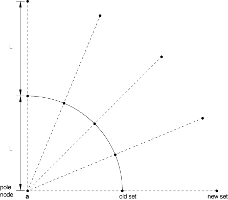
Include this parameter if the new nodes are created by projecting the nodes in the old set from the pole node. Each new node will be located such that the corresponding old node is equidistant between the pole node and the new node.
This parameter is particularly useful for creating nodes associated with infinite elements (Infinite elements).
- REFLECT
-
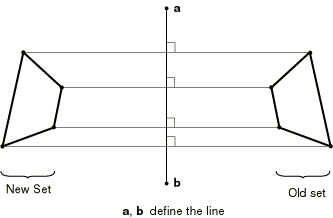
Set REFLECT=LINE to create the new nodes by reflection through a line.
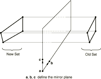
Set REFLECT=MIRROR to create the new nodes by reflection through a plane.
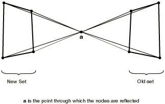
Set REFLECT=POINT to create the new nodes by reflection through a point.
- SHIFT
-
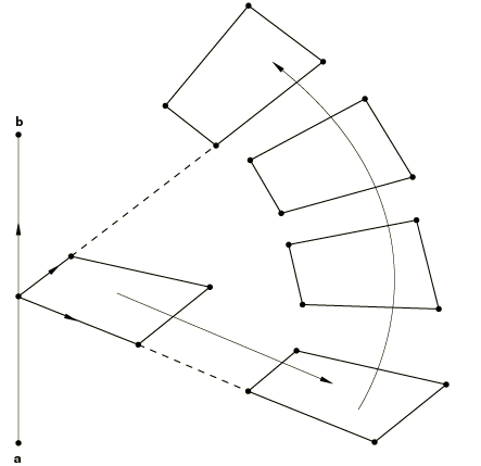
Include this parameter if the new nodes are to be created by translation and/or rotation of the nodes in the old node set. If both translation and rotation are specified, the translation is applied once before the rotation.
![]()
Optional parameters
- MULTIPLE
-
This parameter is used with the SHIFT parameter to define the number of times the rotation should be applied. The default is MULTIPLE=1.
- NEW SET
-
Set this parameter equal to the name of the node set to which the nodes created by the operation will be assigned. This new node set will be unsorted if the OLD SET was unsorted and if the NEW SET does not already exist. Otherwise, this new node set will be a sorted set.
If this parameter is omitted, the newly created nodes are not assigned to a node set.
![]()
Data lines if the SHIFT parameter is included
- First line
-
Value of the translation to be applied in the X-direction.
-
Value of the translation to be applied in the Y-direction.
-
Value of the translation to be applied in the Z-direction.
-
- Second line
-
X-coordinate of the first point defining the rotation axis (point a in Figure 1).
-
Y-coordinate of the first point defining the rotation axis.
-
Z-coordinate of the first point defining the rotation axis.
-
X-coordinate of the second point defining the rotation axis (point b in Figure 1).
-
Y-coordinate of the second point defining the rotation axis.
-
Z-coordinate of the second point defining the rotation axis.
-
Angle of rotation about the axis a–b, in degrees.
-
![]()
Data line if REFLECT=LINE
- First (and only) line
-
X-coordinate of the first point defining the reflection line (point a in Figure 2).
-
Y-coordinate of the first point defining the reflection line.
-
Z-coordinate of the first point defining the reflection line.
-
X-coordinate of the second point defining the reflection line (point b in Figure 2).
-
Y-coordinate of the second point defining the reflection line.
-
Z-coordinate of the second point defining the reflection line.
-
![]()
Data lines if REFLECT=MIRROR
- First line
-
X-coordinate of the first point defining the reflection plane (point a in Figure 3).
-
Y-coordinate of the first point defining the reflection plane.
-
Z-coordinate of the first point defining the reflection plane.
-
X-coordinate of the second point defining the reflection plane (point b in Figure 3).
-
Y-coordinate of the second point defining the reflection plane.
-
Z-coordinate of the second point defining the reflection plane.
-
- Second line
-
X-coordinate of the third point defining the reflection plane (point c in Figure 3).
-
Y-coordinate of the third point defining the reflection plane.
-
Z-coordinate of the third point defining the reflection plane.
-
![]()
Data line if REFLECT=POINT
- First (and only) line
-
X-coordinate of the reflection point (point a in Figure 4).
-
Y-coordinate of the reflection point.
-
Z-coordinate of the reflection point.
-
![]()
Data line if the POLE parameter is included
- First (and only) line
-
-
Number of the pole node (optional: it must have been defined already).
-
X-coordinate of the pole node (point a in Figure 5 only required if the pole node number was not entered).
-
Y-coordinate of the pole node (only required if the pole node number was not entered).
-
Z-coordinate of the pole node (only required if the pole node number was not entered).
-