ProductsAbaqus/StandardAbaqus/ExplicitAbaqus/CAE
TypeModel data in Abaqus/Standard; History data in Abaqus/Explicit
LevelModel in Abaqus/Standard; Step in Abaqus/Explicit
Abaqus/CAEInteraction module
Required parameters
- CPSET
This parameter applies only to Abaqus/Explicit analyses.
Set this parameter equal to the name of the contact pair set name to associate these clearance data with the appropriate contact pairs.
- MASTER
This parameter applies only to Abaqus/Standard analyses.
Set this parameter equal to the name of the master surface of the contact pair.
- SLAVE
This parameter applies only to Abaqus/Standard analyses.
Set this parameter equal to the name of the slave surface of the contact pair.
![]()
Required, mutually exclusive parameters
- TABULAR
Include this parameter to specify the slave nodes or the node sets and their corresponding initial clearance/overclosure values (and, if required, contact directions) on the data lines of this option. In an Abaqus/Explicit analysis only initial clearances are allowed.
- VALUE
Set this parameter equal to the initial clearance/overclosure for the entire set of slave nodes. In Abaqus/Standard a positive value specifies an initial clearance, and a negative value specifies an initial overclosure. In an Abaqus/Explicit analysis this value must be positive since only initial clearances are allowed.
![]()
Optional parameters when the TABULAR parameter is included
- BOLT
Include this parameter to indicate that the appropriate contact normal directions for a threaded bolt connection will be generated automatically based on thread geometry data and two points used to define a direction vector on the axis of the bolt and bolt-hole assembly specified on the data lines. This parameter is valid only for single threaded bolts.
- INPUT
Set this parameter equal to the name of the alternate input file containing the data lines for this option. See Input Syntax Rules for the syntax of such file names. The data lines in the alternate input file should be in the same format as that for the TABULAR parameter.
If this parameter is omitted and the TABULAR parameter is included, it is assumed that the data follow the keyword line.
![]()
Data lines if the TABULAR parameter is included with neither the INPUT parameter nor the BOLT parameter
- First line
Node number or node set label.
Clearance value. (In an Abaqus/Standard analysis a positive value indicates an opening between the surfaces and a negative value indicates overclosure.) If this field is left blank, the clearance value automatically calculated will not be modified.
First component of the normal.
Second component of the normal.
Third component of the normal.
Repeat the above data line as often as necessary to define the clearance value and the direction in which Abaqus tests for contact between the slave node and the corresponding closest point on the master surface. The specification of the normal is optional. If the normal is given, it should be in the direction of the master surface's outward normal. If the normal is not given, Abaqus calculates it from the geometry of the master surface (see Common difficulties associated with contact modeling in Abaqus/Standard and Common difficulties associated with contact modeling using contact pairs in Abaqus/Explicit).
![]()
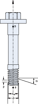
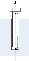
Data lines if both the TABULAR parameter and the BOLT parameter are included without the INPUT parameter (see figures below)
- First line
Half-thread angle, α, (in degrees).
Pitch (thread-to-thread distance), p.
Bolt major thread diameter, d. If the mean diameter is given, the major diameter is ignored.
Bolt mean thread diameter, dm. The default value is d-0.649519p.
- Second line
Node number or node set label.
Clearance value. (In an Abaqus/Standard analysis a positive value indicates an opening between the surfaces and a negative value indicates overclosure.) If this field is left blank, the clearance value calculated automatically will not be modified.
X-coordinate of point a along the axis of the bolt/bolt hole.
Y-coordinate of point a along the axis of the bolt/bolt hole.
Z-coordinate of point a along the axis of the bolt/bolt hole.
X-coordinate of point b along the axis of the bolt/bolt hole.
Y-coordinate of point b along the axis of the bolt/bolt hole.
Z-coordinate of point b along the axis of the bolt/bolt hole.
Repeat the second data line as often as necessary to define the clearance value and the direction vector on the axis of the bolt and bolt-hole assembly that Abaqus uses to calculate the contact normal directions based on the thread geometry (see Adjusting initial surface positions and specifying initial clearances in Abaqus/Standard contact pairs and Specifying initial clearance values precisely).
![]()
To define a clearance value by using the VALUE parameter
No data lines are used with this option when the VALUE parameter is specified.