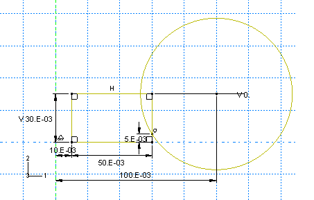
Draw an arbitrary rectangle to the right of the axis of symmetry. Dimension it as follows:
- Set the horizontal distance between the axis of symmetry and the left edge of the rectangle to 0.01 m.
- Set the vertical height of the rectangle to 0.030 m and its horizontal span to 0.050 m.
Sketch a circle using the Create Circle: Center and Perimeter tool  . Select any point to the right of the rectangle as the center, and snap the perimeter point to any point along the right edge of the rectangle. Dimension the circle as follows: . Select any point to the right of the rectangle as the center, and snap the perimeter point to any point along the right edge of the rectangle. Dimension the circle as follows:
- Set the horizontal distance between the axis of symmetry and the center of the circle to 0.1 m.
- Set the vertical distance between the center of the circle and the top-right vertex of the rectangle to 0 m.
- Set the vertical distance between the perimeter point (where the circle snaps to the rectangle) and the bottom-right vertex of the rectangle to 0.005 m.
The sketch appears as shown in Figure 1. Figure 1. Construction geometry used to create the part (with grid spacing doubled).

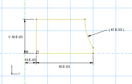
Use the Auto-Trim tool  to remove the excess portions of the sketch as shown in Figure 2. to remove the excess portions of the sketch as shown in Figure 2. Figure 2. Final part geometry (with grid spacing doubled).

|