Displaying a free body cut | ||
| ||
To display the entire model in the viewport, click
 in the
Display Group toolbar.
From the main menu bar, select ToolsFree Body CutManager.
Click Create in the Free Body Cut Manager.
From the dialog box that appears, select 3D element faces as the Selection method and click Continue.
In the Free Body Cross-Section dialog box, select Surfaces as the Item and Pick from viewport as the Method.
In the prompt area, set the selection method to by angle and accept the default angle.
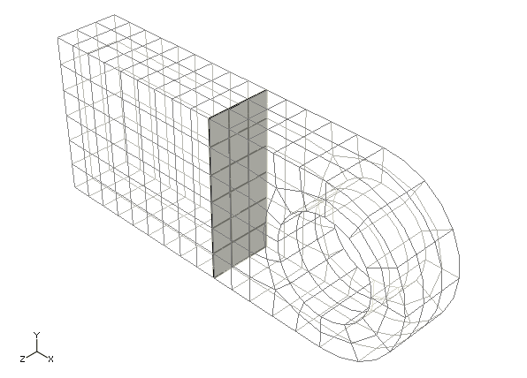
Select the surface, highlighted in Figure 1 to define the free body cut cross-section.
-
From the Selection toolbar, toggle off the
Select the Entity Closest to the Screen tool
 and ensure that the Select From All
Entities tool
 is selected.
-
As you move the cursor in the viewport,
Abaqus/CAE
highlights all of the potential selections and adds ellipsis marks (...) next
to the cursor arrow to indicate an ambiguous selection. Position the cursor so
that one of the faces of the desired surface is highlighted, and click to
display the first surface selection.
Figure 1. The free body cross-section.

- Use the Next and Previous buttons to cycle through the possible selections until the appropriate vertical surface is highlighted, and click OK.
-
From the Selection toolbar, toggle off the
Select the Entity Closest to the Screen tool
Click Done in the prompt area to indicate your selection is complete. Click OK in the Free Body Cross-Section dialog box.
In the Edit Free Body Cut dialog box, accept the default settings for the Summation Point and the Component Resolution. Click OK to close the dialog box.
Click Options in the Free Body Cut Manager.
From the Free Body Plot Options dialog box, select the Force tab in the Color & Style tabbed page. Click the resultant color sample
 to change the color of the resultant force arrow.
Once you have selected a new color for the resultant force arrow, click OK in the Free Body Plot Options dialog box and click Dismiss in the Free Body Cut Manager.
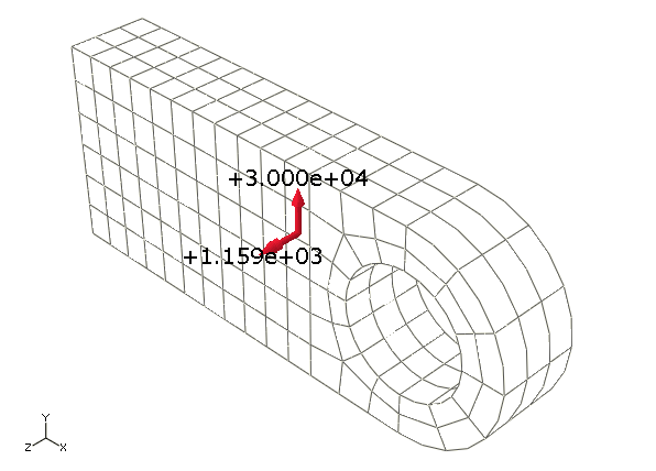
The free body cut is displayed in the viewport, as shown in Figure 2.
Figure 2. Free body cut displayed on the connecting lug.