Defining the material and section properties | ||
| ||
Context:
The circuit board is assumed to be made of a PCB elastic material with a Young's modulus of 45 × 109 Pa and a Poisson's ratio of 0.3. The mass density of the board is 500 kg/m3.
Define a material named PCB with these properties.
The foam packaging material will be modeled using the crushable foam plasticity model. The elastic properties of the packaging include a Young's modulus of 3 × 10⁶ Pa and a Poisson's ratio of 0.0. The material density of the packaging is 100 kg/m3. Define a material named Foam with these properties; do not close the material editor.
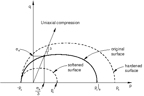
The yield surface of a crushable foam in the p–q (pressure stress-Mises equivalent stress) plane is illustrated in Figure 1.

The initial yield behavior is governed by the ratio of initial yield stress in uniaxial compression to initial yield stress in hydrostatic compression, , and the ratio of yield stress in hydrostatic tension to initial yield stress in hydrostatic compression, . In this problem we have chosen the first data item to be 1.1 and the second data item (which is given as a positive value) to be 0.1.
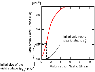
Hardening effects are also included in the material model definition. Table 1 summarizes the yield stress–plastic strain data.
| Yield stress in uniaxial compression (Pa) | Plastic strain |
|---|---|
| 0.22000E6 | 0.0 |
| 0.24651E6 | 0.1 |
| 0.27294E6 | 0.2 |
| 0.29902E6 | 0.3 |
| 0.32455E6 | 0.4 |
| 0.34935E6 | 0.5 |
| 0.37326E6 | 0.6 |
| 0.39617E6 | 0.7 |
| 0.41801E6 | 0.8 |
| 0.43872E6 | 0.9 |
| 0.45827E6 | 1.0 |
| 0.49384E6 | 1.2 |
| 0.52484E6 | 1.4 |
| 0.55153E6 | 1.6 |
| 0.57431E6 | 1.8 |
| 0.59359E6 | 2.0 |
| 0.62936E6 | 2.5 |
| 0.65199E6 | 3.0 |
| 0.68334E6 | 5.0 |
| 0.68833E6 | 10.0 |
The crushable foam hardening model follows the curve shown in Figure 2.

For your convenience, the hardening data are available in a text file named drop-test-foam.txt. Enter the following command at the operating system prompt to use the Abaqus fetch utility to copy the file to your local directory:
abaqus fetch job=drop*.txt
In the material editor, select . Enter the yield stress ratios given above. Click , and select Foam Hardening. Select the first cell in the suboption editor, and click mouse button 3. From the menu that appears, select Read from File. Select the file named drop-test-foam.txt to read the hardening data shown in Table 1.
Define a homogeneous shell section named BoardSection that refers to the material PCB. Specify a thickness of 0.002 m, and assign this section definition to the part Board. Define a homogeneous solid section named FoamSection that refers to the material Foam. Assign this section definition to the part Packaging.
For the circuit board it is most meaningful to output stress results in the longitudinal and lateral directions, aligned with the edges of the board. Therefore, you need to specify a local material orientation for the circuit board mesh.