Creating an assembly, defining an analysis step, and specifying output requests

You will partition the plate in half at its midspan; this will allow you to define a set there. You will also define additional assembly-level sets to facilitate other output request and boundary condition definitions.

This task shows you how to:

Context:

Create a dependent instance of the plate.

Next, create a single static, general step. Name the step Apply Pressure, and specify the following step description: Uniform pressure (20 kPa) load. Accept all the default settings for the step.

Among the output you will need are the nodal displacements, reaction forces, and element stresses as field data. These data will be used to create deformed shape plots, contour plots, and tabular data reports in the Visualization module. You will also want to write the displacements at the midspan as history data to create X–Y plots in the Visualization module.

Partition the plate and define geometry sets

  1. In the Model Tree, double-click the Plate item in the Parts container to make it current.

  2. Partition the plate in half using the Partition Face: Use Shortest Path Between 2 Points tool, . Use the midpoints of the skewed edges of the plate to create the partition shown in Figure 1.
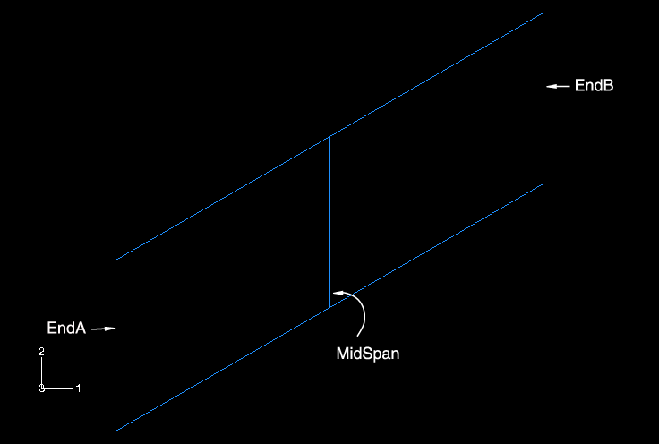
    Figure 1. Partition used to define a geometry set at the plate midspan.

  3. In the Model Tree, expand the Assembly container and double-click the Sets item to create a geometry set for the midspan named MidSpan. Similarly, create sets for the left and right edges of the plate and name them EndA and EndB, respectively. The locations of these three sets are indicated in Figure 1.

    Tip: Geometry sets can be reviewed by expanding the Sets item underneath the Assembly container in the Model Tree and then double-clicking on the set name in the list that appears. The selected set is highlighted in the viewport, and its definition can be edited if necessary.

Change the default output requests

  1. Edit the field output request so that only the nodal displacements, reaction forces, and element stresses and strains for the whole model are written as field data to the .odb file.

  2. Edit the history output request so that only the vertical nodal displacements U3 for the set named MidSpan are written as history data to the .odb file.