Assigning the rigid body reference point

You need to assign a rigid body reference point to the pin. Because you will not assign mass or rotary inertia to the pin, the rigid body reference point can be placed anywhere in the viewport. You use the Load module to apply constraints to the reference point or to define its motion. Motion or constraints that you apply to the rigid body reference point are applied to the entire rigid surface.

Context:

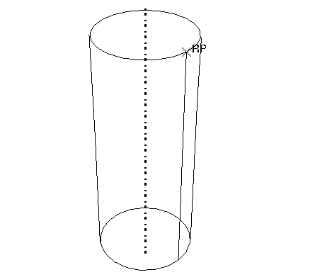
You can either select the reference point from the part in the viewport, or you can enter its coordinates. For the tutorial you will select the reference point from the viewport, as shown in Figure 1.

Figure 1. Create a rigid body reference point on the pin.
  1. From the main menu bar, select ToolsReference Point.

  2. Select one of the vertices on the circumference of the pin.

    Abaqus/CAE labels the vertex RP to indicate that the reference point has been assigned to it.