In the
Model Tree,
expand the Assembly container and double-click the
Surfaces item.
The Create Surface dialog box appears.
In the dialog box, name the surface Pin
and click Continue.
In the viewport, select the pin.
Click mouse button 2 in the viewport to indicate that you have
finished selecting regions for the surface.
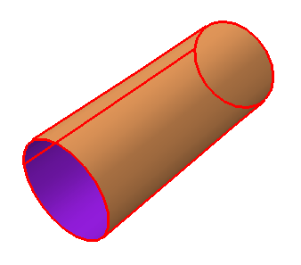
Each side of the hollow cylinder representing the pin has a different
color associated with it. In
Figure 1
the outside of the pin is colored brown and the inside of the pin is colored
purple. The colors may be reversed on your model, depending on how you created
the original sketch for the pin.
Figure 1. Select the region to be defined as the surface
Pin.

You must choose whether the surface consists of the inside or the
outside of the cylinder. The outside surface contacts the two hinges and is the
desired choice. From the buttons in the prompt area, click the color
(Brown or Purple) associated with
the outside surface.
Abaqus/CAE
creates the desired surface called Pin and
displays it underneath the Surfaces container in the
Model Tree.
![]()