Partitioning the flange with the lubrication hole | ||
| ||
Context:
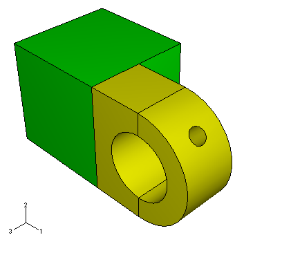
The flange must be partitioned into the regions shown in Figure 1.

Make the hinge piece with the lubrication hole current in the viewport.
From the main menu, select ToolsPartition.
The Create Partition dialog box appears.
You want to partition the entire cell that makes up the flange. From the Create Partition dialog box, select Cell as the Type of partition and click Define cutting plane as the partition Method.
Select the flange of the hinge with the lubrication hole. Click Done to indicate you have finished selecting cells.
Abaqus/CAE provides three methods for specifying the cutting plane:
-
Select a point and a normal. The cutting plane passes through the selected point, normal to the selected edge.
-
Select three non-colinear points. The cutting plane passes through each point.
-
Select an edge and a point along the edge. The cutting plane passes through the selected point, normal to the selected edge.
The cutting plane need not be defined in the cell being partitioned. The plane extends infinitely and partitions the selected cell anywhere there is an intersection.
-
From the buttons in the prompt area, select 3 points.
Abaqus/CAE highlights points that you can select.
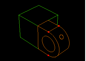
Select three points that cut the flanges in half with a vertical partition, as shown in Figure 2.
Tip: You may find it easier to select the desired points if you magnify, rotate, and pan the model to obtain a more convenient view. Figure 2. Select three points to use in partitioning the flanges.
From the prompt area, click Create Partition.
Abaqus/CAE creates the desired partitions.
The flange regions are colored yellow, indicating that no additional partitions are required to create a hexahedral mesh. Thus, the partitioning operation is complete.
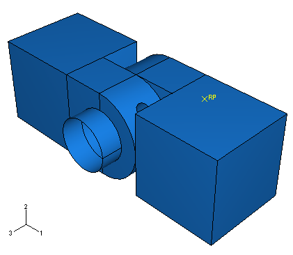
Select Assembly in the Object field of the context bar to display the model assembly in the viewport. The model assembly with all the partitions is shown in Figure 3.
Figure 3. The partitioned model.
Tip: If you did not previously convert the positioning constraints to absolute positions, this partition may invalidate the coaxial constraints created earlier. If necessary, return to the Assembly module and define new coaxial constraints between the hinge pieces and between the hinge and the pin using the technique described earlier. It is also possible that the partition may invalidate the surfaces used for the contact interactions. Review these and correct them as necessary.