Defining the surfaces on the hinge pieces | ||
| ||
Resume the visibility of part instance Hinge-hole-1, and suppress the visibility of Pin-1 (in the Instances container, click mouse button 3 on the instance name, and select Show or Hide as appropriate).
Abaqus/CAE displays only the hinge piece with the lubrication hole in the viewport.
In the Model Tree, double-click Surfaces underneath the Assembly container.
The Create Surface dialog box appears.
In the dialog box, name the surface Flange-h and click Continue.
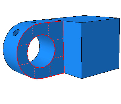
On the instance with the lubrication hole, select the face of the flange that contacts the other flange, as shown by the gridded face in Figure 1. (You may need to rotate the view to see this face clearly.)
Figure 1. Select the region to be defined as the surface Flange-h.
When you have selected the desired face, click mouse button 2 to confirm your selection.
Abaqus/CAE creates the desired surface called Flange-h and displays it underneath the Surfaces container in the Model Tree.
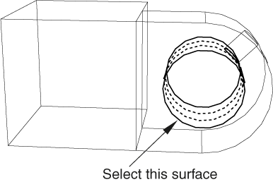
Create a surface called Inside-h that includes the cylindrical inner surface of the hinge piece with the lubrication hole, as shown in Figure 2. (You may need to zoom in on the view to select this face.)
Figure 2. Select the region to be defined as the surface Inside-h.
Change the visibility settings so that only Hinge-solid-1 is visible.
Use similar techniques to create a surface called Flange-s that contains the corresponding face of the solid hinge piece's flange.
Finally, create a surface called Inside-s that includes the cylindrical inner surface of the solid hinge piece.
Return to the default visibility settings (select the three part instance names in the Instances container, and click mouse button 3; from the menu that appears, select Show).