Constraining the hinge piece with the lubrication hole | ||
| ||
In the Model Tree, click mouse button 3 on the BCs container and select Manager from the menu that appears.
The Boundary Condition Manager dialog box appears.
In the Boundary Condition Manager, click Create.
The Create Boundary Condition dialog box appears.
In the Create Boundary Condition dialog box:
- Name the boundary condition Fixed.
- Select Initial from the list of steps.
- Accept Mechanical as the default Category selection.
- Select Displacement/Rotation as the type of boundary condition for the selected step.
- Click Continue.
The Region Selection dialog box appears.
- From the right side of the prompt area, click Select in Viewport to select the object directly from the viewport.
The Region Selection dialog box closes.
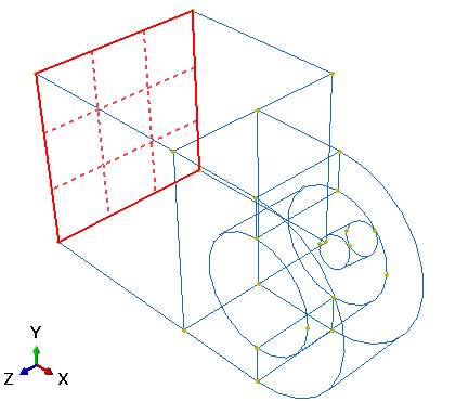
Select the gridded face shown in Figure 1 as the region where the boundary condition will be applied. You may need to rotate the view in order to select this face.
Figure 1. Apply a boundary condition to the end of the hinge piece with the lubrication hole.
Click mouse button 2 to indicate that you have finished selecting regions.
The Edit Boundary Condition dialog box appears.
In the dialog box:
- Toggle on the buttons labeled U1, U2, and U3 to constrain the end of the hinge in the 1-, 2-, and 3-directions. You do not need to constrain the rotational degrees of freedom of the hinge because solid elements (which have only translational degrees of freedom) will be used to mesh the hinge.
- Click OK to close the dialog box.
The boundary condition that you just created appears in the Boundary Condition Manager, and arrows appear on the nodes of the face indicating the constrained degrees of freedom. The Boundary Condition Manager shows that the boundary condition remains active in all steps of the analysis.
Tip: To suppress the display of boundary condition arrows, click the Attribute tab in the Assembly Display Options dialog box to access the boundary condition display options.