Adding the flange to the base feature | ||
| ||
Context:
You select one face of the cube to define the sketch plane and extrude the sketched profile through half the depth of the cube. The cube and flange are shown in Figure 1.

From the main menu bar, select ShapeSolidExtrude.
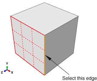
Select the face at the front of the cube to define the sketching plane, as shown in Figure 2.
Figure 2. Select the gridded face to define the sketching plane. Select the indicated edge to position the part correctly in the Sketcher.
When you stop moving the cursor during a selection procedure, Abaqus/CAE highlights the edges of the entity that it would select at the current cursor position. This highlighting behavior is called preselection.
Note:
Two forms of preselection are available in Abaqus/CAE: one for object selection from the viewport and the other for selection from the Sketcher. For more information, see Highlighting objects prior to selection, and Turning preselection on or off, respectively.
Select an edge that will appear vertical and on the right side of the sketch, as shown in Figure 2.
Again, Abaqus/CAE uses preselection to aid you in selecting the desired edge.
The Sketcher starts and displays the outline of the base feature as reference geometry. Abaqus/CAE magnifies the view to fit the sketch plane; the sheet size and grid spacing are also recalculated based on the size of the sketch plane. To change the sheet size and grid spacing back to their original settings and disable their automatic recalculation for the current session, use the options tool
 , located in the
Sketcher
toolbox. On the General tabbed page, toggle off
Auto next to the sheet size text field and set the value
to 0.2; toggle off Auto
next to the grid spacing text field and set the value to
0.005.
Tip: To retain the original sheet size and grid spacing for all sketches in a part, you can select the options tool while sketching the base feature—the cube—and toggle off both Auto settings. The sketch of the flange that you will create is illustrated in Figure 3. To duplicate the view in the figure, use the options tool again to double the grid spacing.
Figure 3. Use the Sketcher to create the flange profile.
Zoom out to view the area where you will sketch the flange:
-
From the
View Manipulation toolbar,
select the magnify tool
 .
.
- Position the cursor near the center of the viewport.
- Click mouse button 1 and drag to the left until the cube occupies approximately half of the visible Sketcher space.
Reducing the view is necessary because the flange is created beyond the edges of the selected sketch plane.
-
From the
View Manipulation toolbar,
select the magnify tool
As before, the approximate shape of the new feature will be sketched first. From the Sketcher toolbox, select the connected lines tool
 .
.
Sketch the rectangular portion of the flange by drawing three lines as follows:
- Starting at any point to the right of the cube, connect the line to the top-right corner of the cube.
- Continue the next line to the bottom-right corner of the cube. This line is automatically assigned a vertical constraint.
- The final line extends from the bottom-right corner of the cube to any point to the right of the cube.
Tip: If you make a mistake while sketching, use the Sketcher undo  or delete
 tools to correct your error.
Click mouse button 2 in the viewport to exit the connected lines tool.
Refine the sketch by defining the following constraints and dimension:
-
Use the constraints tool
 to constrain the top and bottom lines of the sketch so that
each is horizontal.
- Assign an equal length constraint to these two lines (use ShiftClick to select both lines).
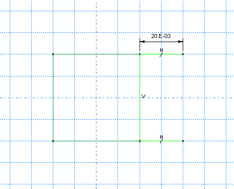
- Dimension either line so that it is 0.02 m long.
The sketch appears as shown in Figure 4.
Figure 4. Draw the rectangular portion of the flange.
-
Use the constraints tool
Close the profile by adding a semicircular arc using the 3-points circle tool
 .
.
- Select the two vertices at the open end of the rectangle as the endpoints of the arc, starting with the top one. Select any point to the right of the sketch as a point that lies on the arc.
- Define tangent constraints between the ends of the arc and the horizontal lines to refine the sketch.
Click mouse button 2 in the viewport to exit the 3-points circle tool.
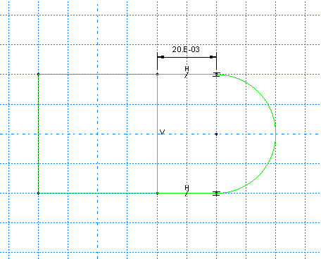
The resulting arc is shown in Figure 5.
Figure 5. Add the curved portion of the flange.
From the Sketcher toolbox, select the center-perimeter circle tool
 to sketch the flange hole.
- Place the center of the circle to coincide approximately with the center of the arc created previously. The perimeter point should be placed to the right of the center point. Apply a concentric constraint between the two circular regions.
-
Use the dimension tool
 to change the value of the radius to
0.01 m.
-
Dimension the vertical distance between the center of each circle
and its perimeter point. Edit this dimension so that the distance is
0. (If the distance is already
0, you cannot add a vertical dimension.) This
will adjust the location of the perimeter point so that it is on the same
horizontal plane as the center point.
Note:
When you mesh a part, Abaqus/CAE places nodes wherever vertices appear along an edge; therefore, the location of the vertex on the circumference of the circle influences the final mesh. Placing it on the same horizontal plane as the center point results in a high-quality mesh.
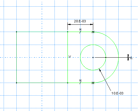
The final sketch is shown in Figure 6.
Figure 6. Final sketch.
Click mouse button 2 to exit the Sketcher.
Abaqus/CAE displays the part in an isometric view showing the base extrusion, your sketched profile, and an arrow indicating the extrusion direction. The default extrusion direction for a solid is always out of the solid. Abaqus/CAE also displays the Edit Extrusion dialog box.
Tip: Use the auto-fit view manipulation tool  to fit the sketched flange profile and the base extrusion in
the viewport.
In the Edit Extrusion dialog box:
- Accept the default Type selection of Blind to indicate that you will provide the depth of the extrusion.
- In the Depth field, type an extrusion depth of 0.02.
-
Click
 to reverse the extrusion direction, as shown in
Figure 7.
Figure 7. Completed flange sketch showing the extrusion direction.
- Toggle on Keep internal boundaries. When you toggle this option on, Abaqus/CAE maintains the face that is generated between the extruded solid feature and the existing part. As a result, the extruded flange is maintained as a second cell and is not merged with the cube. (When you mesh the model at the end of the tutorial, the internal boundary allows you to mesh the flange without having to first partition the cell and flange into separate cells.)
-
Click OK to create the solid extrusion.
Abaqus/CAE displays the part composed of the cube and the flange. Use the auto-fit view manipulation tool
 again to resize the part to fit in the viewport.