Context:
You will start the cantilever beam tutorial by creating a three-dimensional, deformable solid body. You do this by sketching the two-dimensional profile of the beam (a rectangle) and extruding it. Abaqus/CAE automatically enters the Sketcher when you create a part.
Abaqus/CAE often displays a short message in the prompt area indicating what it expects you to do next, as shown in Figure 1.
Figure 1. Messages and instructions are displayed in the prompt area.
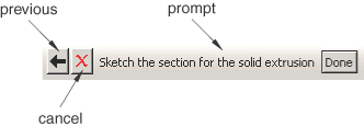
Click the Cancel button to cancel the current task. Click the Previous button to cancel the current step in the task and return to the previous step.
If you did not already start Abaqus/CAE, type abaqus cae. Resize your windows so that you can follow the tutorial and see the Abaqus/CAE main window.
From the Create Model Database options in the Start Session dialog box that appears, select With Standard/Explicit Model. If you are already in an Abaqus/CAE session, select from the main menu bar.
Abaqus/CAE enters the Part module. The Model Tree appears in the left side of the main window. Between the Model Tree and the canvas is the Part module toolbox. A toolbox contains a set of icons that allow expert users to bypass the menus in the main menu bar. For many tools, as you select an item from the main menu bar or the Model Tree, the corresponding tool is highlighted in the module toolbox so you can learn its location.
In the Model Tree, double-click the Parts container to create a new part.
The Create Part dialog box appears. Abaqus/CAE also displays text in the prompt area near the bottom of the window to guide you through the procedure.
You use the Create Part dialog box to name the part; to choose its modeling space, type, and base feature; and to set the approximate size. You can edit and rename a part after you create it; you can also change its modeling space and type but not its base feature.
Name the part Beam. Accept the default settings of a three-dimensional, deformable body and a solid, extruded base feature. In the Approximate size text field, type 300.
Click Continue to exit the Create Part dialog box.
Abaqus/CAE automatically enters the Sketcher. The Sketcher toolbox appears in the left side of the main window, and the Sketcher grid appears in the viewport. The Sketcher contains a set of basic tools that allow you to sketch the two-dimensional profile of your part. Abaqus/CAE enters the Sketcher whenever you create or edit a part. To finish using a Sketcher tool, click mouse button 2 in the viewport or select a new tool.
The following aspects of the Sketcher help you sketch the desired geometry:
-
The Sketcher grid helps you position the cursor and align objects in the viewport.
-
Dashed lines indicate the X- and Y-axes of the sketch and intersect at the origin of the sketch.
-
A triad in the lower-left corner of the viewport indicates the relationship between the sketch plane and the orientation of the part.
-
When you select a sketching tool, Abaqus/CAE displays the X- and Y-coordinates of the cursor in the upper-left corner of the viewport.
To sketch the profile of the cantilever beam, you need to select the rectangle drawing tool  .
.
The rectangle drawing tool appears in the Sketcher toolbox with a white background indicating that you selected it. Abaqus/CAE displays prompts in the prompt area to guide you through the procedure.
In the viewport, sketch the rectangle using the following steps:
- You will first sketch a rough approximation of the beam and then use constraints and dimensions to refine the sketch. Select any two points as the opposite corners of the rectangle.
- Click mouse button 2 anywhere in the viewport to exit the rectangle tool.
Note:
If you are a Windows user with a 2-button mouse, press both mouse buttons simultaneously whenever you are asked to press mouse button 2.
- The Sketcher automatically adds constraints to the sketch (in this case the four corners of the rectangle are assigned perpendicular constraints and one edge is designated as horizontal).
- Use the dimension tool
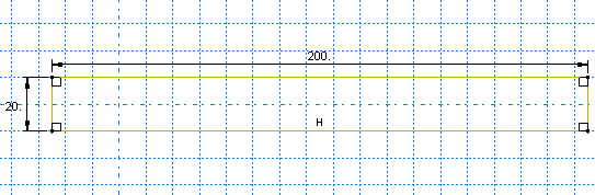
 to dimension the top and left edges of the rectangle. The top edge should have a horizontal dimension of 200 mm, and the left edge should have a vertical dimension of 20 mm. When dimensioning each edge, simply select the line, click mouse button 1 to position the dimension text, and then enter the new dimension in the prompt area.
- The final sketch is shown in Figure 2.
Figure 2. Sketch of the rectangle.
If you make a mistake while using the Sketcher, you can delete lines in your sketch, as explained in the following procedure:
- From the Sketcher toolbox, click the Delete tool,
 .
.
- From the sketch, click a line to select it.
Abaqus/CAE highlights the selected line in red.
- Click mouse button 2 in the viewport to delete the selected line.
- Repeat steps b and c as often as necessary.
- Click mouse button 2 in the viewport to finish using the Delete tool.
Note:
You can also use the Undo tool  and the Redo tool
  to undo and redo your previous operations.
From the prompt area (near the bottom of the main window), click Done to exit the Sketcher.
Note:
If you don't see the Done button in the prompt area, continue to click mouse button 2 in the viewport until it appears.
Because you are creating an extruded part, Abaqus/CAE displays the Edit Base Extrusion dialog box for you to select the depth. Optional parameters to modify the extrusion shape are also available. In the Depth field, erase the default value and type a value of 25.0. Click OK to accept this value.
Abaqus/CAE displays an isometric view of the new part, as shown in Figure 3.
Figure 3. Isometric view of the beam.
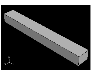
To help you orient the cantilever beam during the modeling process, Abaqus/CAE displays a triad in the lower-left corner indicating the orientation of the global coordinate system.
Before you continue the tutorial, save your model in a model database file.
- From the main menu bar, select . The Save Model Database As dialog box appears.
- Type a name for the new model database in the File Name field, and click OK. You do not need to include the file extension; Abaqus/CAE automatically appends .cae to the file name.
Abaqus/CAE stores the model database in a new file and returns to the Part module. The title bar of the Abaqus/CAE window displays the path and name of the model database. You should always save your model database at regular intervals (for example, each time you switch modules).