Creating a part | ||
| ||
Context:
You will start the overhead hoist problem by creating a two-dimensional, deformable wire part. You do this by sketching the geometry of the frame. Abaqus/CAE automatically enters the Sketcher when you create a part.
Abaqus/CAE often displays a short message in the prompt area indicating what you should do next, as shown in Figure 1.
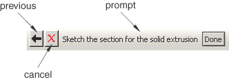
Click the button to cancel the current task. Click the button to cancel the current step in the task and return to the previous step.
You will first sketch a rough approximation of the frame and later use constraints and dimensions to refine the sketch. Begin by using the Create Lines: Rectangle tool
 located in the upper-right region of the Sketcher toolbox to sketch an arbitrary rectangle. Select any two points as the opposite corners of the rectangle.
Click mouse button 2 anywhere in the viewport to exit the rectangle tool.
Note:
If you make a mistake while using the Sketcher, you can undo your last action using the tool
 or delete individual entities of your sketch using the tool
  .
.The Sketcher automatically adds constraints to the sketch as indicated in Figure 2 (in this case, the four corners of the rectangle are assigned perpendicular constraints and one edge is designated as horizontal).
Figure 2. Constraints indicated in the Sketcher.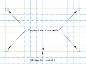
To proceed, the perpendicular constraints must be deleted. In the Sketcher toolbox, select the Delete tool
and then do the following:- In the prompt area, select Constraints as the scope of the operation.
- Using Shift, select the four perpendicular constraints.
- Click in the prompt area.
You will now add additional constraints and dimensions to refine the sketch. Constraints and dimensions allow you to control your sketch geometry and add precision. For more information on constraints and dimensions, see Controlling sketch geometry.
- Use the Add Constraint tool
 to constrain the top and bottom edges so they remain parallel to each other:
In the Add Constraint dialog box, select Parallel.
In the viewport, select the top and bottom edges of the sketch (using Shift).
Click in the prompt area.
- Use the Add Dimension tool
 to dimension the top and bottom edges of the rectangle. The top edge should have a horizontal dimension of 1 m and the bottom edge a horizontal dimension of 2 m. When dimensioning each edge, simply select the line, click mouse button 1 to position the dimension text, and then enter the new dimension in the prompt area. Selecting the line rather than its endpoints constrains the length of the line regardless of its orientation in space (in effect, defining an oblique dimension).
Reset the view as needed using the Auto-Fit View tool
 in the View Manipulation toolbar to see the updated sketch.
 - Dimension the left and right edges so they each have an oblique dimension of 1 m.
The sketch in its current state is shown in Figure 3. In this figure the default grid spacing has been doubled. For information on using the Sketcher Options tool
 to modify the Sketcher display, see Customizing the Sketcher.Figure 3. Rough sketch of frame (with grid spacing doubled).
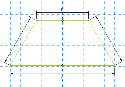
- Use the Add Constraint tool
Now sketch the interior edges of the frame.
- Using the Create Lines: Connected tool
 located in the upper-right corner of the Sketcher toolbox, create two lines as follows:
Start the first line at the upper-left corner of the sketch and extend it to any point that snaps onto the bottom edge (its horizontal location is arbitrary).
Continue the second line to the upper-right corner of the sketch.
Click mouse button 2 anywhere in the viewport to exit the connected lines tool.
- Using the Split tool
 , split the bottom edge at the point where it intersects the two lines created above:
Note the small black triangles at the base of some of the toolbox icons. These triangles indicate the presence of hidden icons that can be revealed. Click and hold the Auto-Trim tool
 located on the middle-right of the Sketcher toolbox until additional icons appear.
From the set of additional icons, click the Split tool
.The split tool appears in the Sketcher toolbox with a white background indicating that you selected it.
Select the bottom edge as the first entity to define the split point.
Select either of the two interior lines as the second entity (a red circle will appear around the split point).
Click mouse button 2 to indicate that you have finished using the split tool.
- Use the Add Constraint tool to constrain the two segments of the bottom edge so they are of equal length:
In the Add Constraint dialog box, select Equal length.
In the viewport, select the two segments of the bottom edge.
Click in the prompt area.
- Using the Create Lines: Connected tool
The final sketch is shown in Figure 4.
Figure 4. Frame geometry sketch.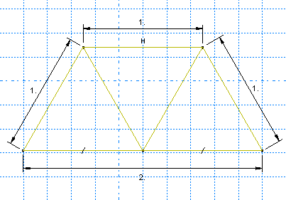
You should always save your model database at regular intervals (for example, each time you switch modules); Abaqus/CAE does not save your model database automatically.