Shell thickness and section points | ||
| ||
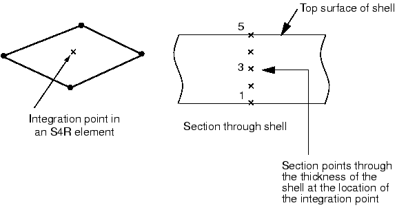
If you choose to have the stiffness calculated during the analysis, Abaqus uses numerical integration to calculate the stresses and strains independently at each section point (integration point) through the thickness of the shell, thus allowing nonlinear material behavior. For example, an elastic-plastic shell may yield at the outer section points while remaining elastic at the inner section points. The location of the single integration point in an S4R (4-node, reduced integration) element and the configuration of the section points through the shell thickness are shown in Figure 1.

You can specify any odd number of section points through the shell thickness when the properties are integrated during the analysis. By default, Abaqus uses five section points through the thickness of a homogeneous shell, which is sufficient for most nonlinear design problems. However, you should use more section points in some complicated simulations, especially when you anticipate reversed plastic bending (nine is normally sufficient in this case). For linear problems three section points provide exact integration through the thickness. However, calculating the material stiffness once at the beginning of the analysis is more efficient for linear elastic shells.
The material behavior must be linear elastic when the stiffness of the cross-section is calculated only at the beginning of the simulation. In this case all calculations are done in terms of the resultant forces and moments across the entire cross-section. If you request stress or strain output, Abaqus provides default output for the bottom surface, the midplane, and the top surface.