Shell formulation – thick or thin | ||
| ||

Abaqus offers multiple classes of shell elements, distinguished by the element's applicability to thin and thick shell problems. General-purpose shell elements are valid for use with both thick and thin shell problems. In certain cases, for specific applications, enhanced performance can be obtained by using the special-purpose shell elements available in Abaqus/Standard.
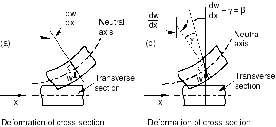
The special-purpose shell elements fall into two categories: thin-only shell elements and thick-only shell elements. All special-purpose shell elements provide for arbitrarily large rotations but only small strains. The thin-only shell elements enforce the Kirchhoff constraint; that is, plane sections normal to the midsection of the shell remain normal to the midsurface. The Kirchhoff constraint is enforced either analytically in the element formulation (STRI3) or numerically through the use of a penalty constraint. The thick-only shell elements are second-order quadrilaterals that may produce more accurate results than the general-purpose shell elements in small-strain applications where the loading is such that the solution is smoothly varying over the span of the shell.
To decide if a given application is a thin or thick shell problem, we can offer a few guidelines. For thick shells transverse shear flexibility is important, while for thin shells it is negligible. The significance of transverse shear in a shell can be estimated by its thickness-to-span ratio. A shell made of a single isotropic material with a ratio greater than 1/15 is considered “thick”; if the ratio is less than 1/15, the shell is considered “thin.” These estimates are approximate; you should always check the transverse shear effects in your model to verify the assumed shell behavior. Since transverse shear flexibility can be significant in laminated composite shell structures, this ratio should be much smaller for “thin” shell theory to apply. Composite shells with very compliant interior layers (so-called “sandwich” composites) have very low transverse shear stiffness and should almost always be modeled with “thick” shells; if the assumption of plane sections remaining plane is violated, continuum elements should be used. See Shell section behavior, for details on checking the validity of using shell theory.
Transverse shear force and strain are available for general-purpose and thick-only shell elements. For three-dimensional elements, estimates of transverse shear stress are provided. The calculation of these stresses neglects coupling between bending and twisting deformation and assumes small spatial gradients of material properties and bending moments.