Reduced integration | ||
| ||
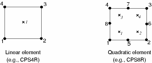
Reduced-integration elements use one fewer integration point in each direction than the fully integrated elements. Reduced-integration, linear elements have just a single integration point located at the element's centroid. (Actually, these first-order elements in Abaqus use the more accurate “uniform strain” formulation, where average values of the strain components are computed for the element. This distinction is not important for this discussion.) The locations of the integration points for reduced-integration, quadrilateral elements are shown in Figure 1.

Abaqus simulations of the cantilever beam problem were performed using the reduced-integration versions of the same four elements utilized previously and using the four finite element meshes shown in Figure 2. The results from these simulations are presented in Table 1.
| Element | Mesh Size (Depth × Length) | |||
|---|---|---|---|---|
| 1 × 6 | 2 × 12 | 4 × 12 | 8 × 24 | |
| CPS4R | 20.3* | 1.308 | 1.051 | 1.012 |
| CPS8R | 1.000 | 1.000 | 1.000 | 1.000 |
| C3D8R | 70.1* | 1.323 | 1.063 | 1.015 |
| C3D20R | 0.999** | 1.000 | 1.000 | 1.000 |
| * no stiffness to resist the applied load, ** two elements through width | ||||
Linear reduced-integration elements tend to be too flexible because they suffer from their own numerical problem called hourglassing. Again, consider a single reduced-integration element modeling a small piece of material subjected to pure bending (see Figure 2).

Neither of the dotted visualization lines has changed in length, and the angle between them is also unchanged, which means that all components of stress at the element's single integration point are zero. This bending mode of deformation is thus a zero-energy mode because no strain energy is generated by this element distortion. The element is unable to resist this type of deformation since it has no stiffness in this mode. In coarse meshes this zero-energy mode can propagate through the mesh, producing meaningless results.
In Abaqus a small amount of artificial “hourglass stiffness” is introduced in first-order reduced-integration elements to limit the propagation of hourglass modes. This stiffness is more effective at limiting the hourglass modes when more elements are used in the model, which means that linear reduced-integration elements can give acceptable results as long as a reasonably fine mesh is used. The errors seen with the finer meshes of linear reduced-integration elements (see Table 1) are within an acceptable range for many applications. The results suggest that at least four elements should be used through the thickness when modeling any structures carrying bending loads with this type of element. When a single linear reduced-integration element is used through the thickness of the beam, all the integration points lie on the neutral axis and the model is unable to resist bending loads. (These cases are marked with a * in Table 1.)
Linear reduced-integration elements are very tolerant of distortion; therefore, use a fine mesh of these elements in any simulation where the distortion levels may be very high.
The quadratic reduced-integration elements available in Abaqus/Standard also have hourglass modes. However, the modes are almost impossible to propagate in a normal mesh and are rarely a problem if the mesh is sufficiently fine. The 1 × 6 mesh of C3D20R elements fails to converge because of hourglassing unless two elements are used through the width, but the more refined meshes do not fail even when only one element is used through the width. Quadratic reduced-integration elements are not susceptible to locking, even when subjected to complicated states of stress. Therefore, these elements are generally the best choice for most general stress/displacement simulations, except in large-displacement simulations involving very large strains and in some types of contact analyses.