Creating the mesh and defining a job | ||
| ||

You must answer the following questions before selecting an element type: Is the plate thin or thick? Are the strains small or large? The plate is quite thin, with a thickness-to-minimum span ratio of 0.02. (The thickness is 0.8 cm and the minimum span is 40 cm.) While we cannot readily predict the magnitude of the strains in the structure, we think that the strains will be small. Based on this information, choose quadratic shell elements (S8R5) because they give accurate results for thin shells in small-strain simulations. For further details on shell element selection, refer to Choosing a shell element.
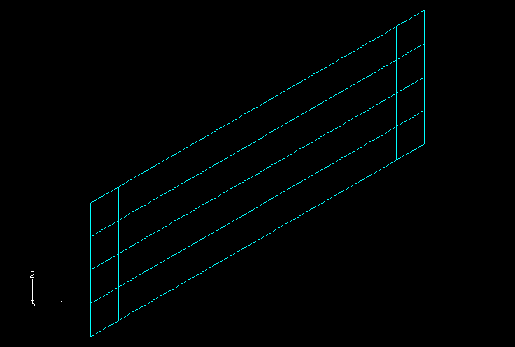
In the Model Tree, expand the Plate item underneath the Parts container and double-click Mesh in the list that appears. Seed the part using a global element size of 0.1. Create a quadrilateral mesh using quadratic, reduced-integration shell elements with five degrees of freedom per node (S8R5).
Before proceeding, rename the model to Linear. This model will later form the basis of the model used in the skew plate example discussed in Nonlinearity.
Define a job named SkewPlate with the following description:
Linear Elastic Skew Plate. 20 kPa Load.
Save your model in a model database file named SkewPlate.cae.
Submit the job for analysis, and monitor the solution progress; correct any modeling errors detected by the analysis product, and investigate the cause of any warnings.