Simulation of the forming of a channel | ||
| ||
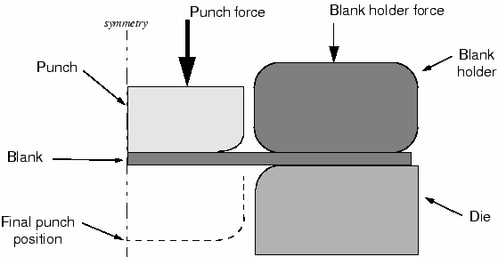
The problem consists of a strip of deformable material, called the blank, and the tools—the punch, die, and blank holder—that contact the blank. The tools are modeled as (analytical) rigid surfaces because they are much stiffer than the blank. Figure 1 shows the basic arrangement of the components.

The blank is 1 mm thick and is squeezed between the blank holder and the die. The blank holder force is 440 kN. This force, in conjunction with the friction between the blank and blank holder and the blank and die, controls how the blank material is drawn into the die during the forming process. You have been asked to determine the forces acting on the punch during the forming process. You also must assess how well the channel is formed with these particular settings for the blank holder force and the coefficient of friction between the tools and blank.
A two-dimensional, plane strain model will be used. The assumption that there is no strain in the out-of-plane direction of the model is valid if the structure is long in this direction. Only half of the channel needs to be modeled because the forming process is symmetric about a plane along the center of the channel.
The model will use contact pairs rather than general contact, since general contact is not available for analytical rigid surfaces in Abaqus/Standard.
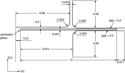
The dimensions of the various components are shown in Figure 2.
