Understanding the Model Tree | ||
| ||
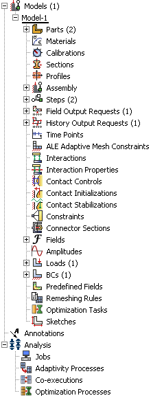
Items in the Model Tree are represented by small icons; for example, the Steps icon, . In addition, parentheses next to an item indicate that the item is a container, and the number in the parentheses indicates the number of items in the container. You can click on the “” and “−” signs in the Model Tree to expand and collapse a container. The right and left arrow keys perform the same operation.
The arrangement of the containers and items in the Model Tree reflects the order in which you are expected to create your model. As noted earlier, a similar logic governs the order of modules in the module menu—you create parts before you create the assembly, and you create steps before you create loads. This arrangement is fixed—you cannot move items in the Model Tree.
The Model Tree provides most of the functionality of the main menu bar and the module managers. For example, if you double-click on the Parts container, you can create a new part (the equivalent of selecting from the main menu bar).
The instructions for the examples that follow will focus on using the Model Tree to access the functionality of Abaqus/CAE. Menu bar actions will be considered only when necessary (e.g., when creating a finite element mesh or postprocessing results).