Torsional response—warping | ||
| ||
The response of a beam to torsion depends on the shape of its cross-section. Generally, torsion in a beam produces warping or nonuniform out-of-plane displacements in the cross-section. Abaqus considers the effects of torsion and warping only in the three-dimensional elements. The warping calculation assumes that the warping displacements are small. The following cross-sections behave differently under torsion: solid cross-sections; closed, thin-walled cross-sections; and open, thin-walled cross-sections.
- Solid cross-sections
A solid, non-circular cross-section does not remain plane under torsion; instead, the section warps. Abaqus uses St. Venant warping theory to calculate a single component of shear strain caused by the warping at each section point in the cross-section. The warping in such solid cross-sections is considered unconstrained and creates negligible axial stresses. (Warping constraints would affect the solution only in the immediate vicinity of the constrained end.) The torsional stiffness of a beam with a solid cross-section depends on the shear modulus, G, of the material and the torsion constant, J, of the beam section. The torsion constant depends on the shape and the warping characteristics of the beam cross-section. Torsional loads that produce large amounts of inelastic deformation in the cross-section cannot be modeled accurately with this approach.
- Closed, thin-walled cross-sections
Beams that have closed, thin-walled, non-circular cross-sections (BOX or HEX) have significant torsional stiffness and, thus, behave in a manner similar to solid sections. Abaqus assumes that warping in these sections is also unconstrained. The thin-walled nature of the cross-section allows Abaqus to consider the shear strains to be constant through the wall thickness. The thin-walled assumption is generally valid provided that the wall thickness is 1/10 a typical beam cross-section dimension. Examples of typical cross-section dimensions for thin-walled cross-sections include:
The diameter of a pipe section.
The length of an edge of a box section.
The typical edge length of an arbitrary section.
- Open, thin-walled cross-sections
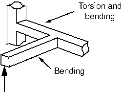
Open, thin-walled cross-sections are very flexible in torsion when warping is unconstrained, and the primary source of torsional stiffness in such structures is the constraint of the axial warping strains. Constraining the warping of open, thin-walled beams introduces axial stresses that can affect the beam's response to other loading types. Abaqus/Standard has shear deformable beam elements, B31OS and B32OS, which include the warping effects in open, thin-walled sections. These elements must be used when modeling structures with open, thin-walled cross-sections—such as a channel (defined as an ARBITRARY section) or an I-section—that are subjected to significant torsional loading.
The variation of the warping-induced axial deformation over the beam's cross-section is defined by the section's warping function. The magnitude of this function is treated as an extra degree of freedom, 7, in the open-section beam elements. Constraining this degree of freedom prevents warping at the nodes at which the constraints are applied.
So that the warping amplitude can be different in each branch, the junction between open-section beams in a frame structure generally should be modeled with separate nodes for each branch (see Figure 2).
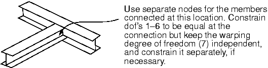
However, if the connection is designed to prevent warping, all branches should share a common node, and the warping degree of freedom should be constrained.
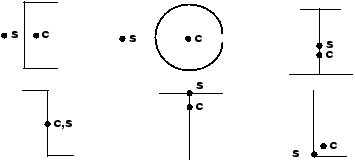
A shear force that does not act through the beam's shear center produces torsion. The twisting moment is equal to the shear force multiplied by its eccentricity with respect to the shear center. Often, the centroid and the shear center do not coincide in open, thin-walled beam sections (see Figure 3). If the nodes are not located at the shear center of the cross-section, the section may twist under loading.