Cargo crane analysis | ||
| ||
A light-service cargo crane is shown in Figure 1. The crane consists of two truss structures joined together by cross bracing. The two main members in each truss structure are steel box beams (box cross-sections). Each truss structure is stiffened by internal bracing, which is welded to the main members. The cross bracing connecting the two truss structures is bolted to the truss structures. These connections can transmit little, if any, moment and, therefore, are treated as pinned joints.
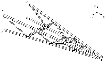
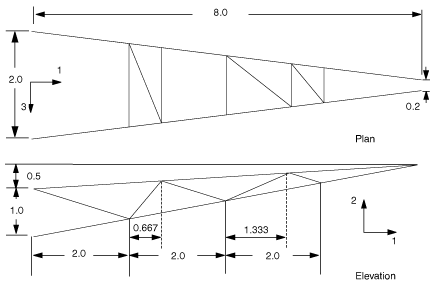
Both the internal bracing and cross bracing use steel box beams with smaller cross-sections than the main members of the truss structures. The two truss structures are connected at their ends (at point E) in such a way that allows independent movement in the 3-direction and all of the rotations, while constraining the displacements in the 1- and 2-directions to be the same. The crane is welded firmly to a massive structure at points A, B, C, and D. The dimensions of the crane are shown in Figure 2. In the following figures, truss A is the structure consisting of members AE, BE, and their internal bracing; and truss B consists of members CE, DE, and their internal bracing.
The ratio of the typical cross-section dimension to global axial length in the main members of the crane is much less than 1/15. The ratio is approximately 1/15 in the shortest member used for internal bracing. Therefore, it is valid to use beam elements to model the crane.