Beam normals | ||
| ||
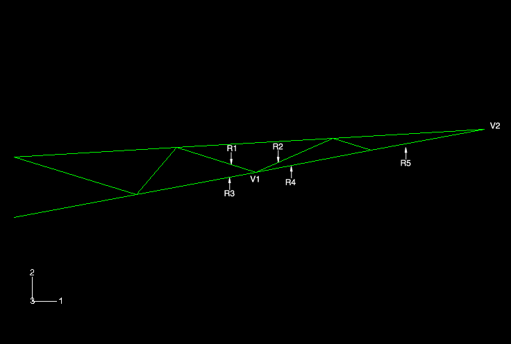
Figure 1 shows the geometry of the truss structure.

Referring to this figure, the correct geometry for the crane model requires three independent beam normals at vertex V1: one each for regions R1 and R2 and a single normal for regions R3 and R4. Using the Abaqus logic for averaging normals, it becomes readily apparent that the beam normal at vertex V1 in region R2 would be averaged with the normals at this point for the adjacent regions. In this case the important part of the averaging logic is that normals that subtend an angle less than 20° with the reference normal are averaged with the reference normal to define a new reference normal. Assume the original reference normal at this point is the normal for regions R3 and R4. Since the normal at vertex V1 in region R2 subtends an angle less than 20° with the original reference normal, it is averaged with the original normal to define a new reference normal at that location. On the other hand, since the normal at vertex V1 in region R1 subtends an angle of approximately 30° with the original reference normal, it will have an independent normal.
As a result of the incorrect average normal, the elements created on regions R2, R3, and R4 that share the node created at vertex V1 would have an intended geometry that exhibits curvature from one end of the element to the other. To prevent Abaqus from applying its averaging algorithm, specify the normal directions explicitly at positions where the subtended angle between adjacent regions will be less than 20°. In this problem you must specify the normal positions for the corresponding regions on both sides of the crane.
There is also a problem with the normals at vertex V2 at the tip of the truss structure, again because the angle between the two regions attached to this vertex is less than 20°. Since we are modeling straight beams, the normals are constant at both ends of each beam. This can be corrected by explicitly specifying the beam normal direction. As before, you must do this for the corresponding regions on both sides of the crane.
Currently, the only way to specify beam normal directions in Abaqus/CAE is with the Keywords Editor. The Keywords Editor is a specialized text editor that allows you to modify the Abaqus input file generated by Abaqus/CAE before submitting it for analysis. Thus, it allows you to add Abaqus/Standard or Abaqus/Explicit functionality when such functionality is not supported by the current release of Abaqus/CAE. For more information on the Keywords Editor, see Adding unsupported keywords to your Abaqus/CAE model.
You will specify the beam normal directions later.