Creation of a perturbed mesh from original coordinate data and eigenvectors: FPERT | ||
| ||
ProductsAbaqus/Standard
General description
Collapse studies of a structure's postbuckling load-displacement (Riks) behavior are often conducted to verify that the critical buckling load and mode predicted by an eigenvalue buckling analysis are accurate. They are also done to investigate the effect of an initial geometric imperfection on the load-displacement response. A typical assumption is that an imperfection made up of a combination of the eigenmodes associated with the lowest eigenvalues will be the most critical. One method of introducing an imperfection of this type into the model is by adding to the original mesh coordinates. In this case is the ith eigenmode, is a scaling factor of the ith eigenmode, and M is the total number of eigenmodes extracted in the buckling analysis. Since the eigenvector is typically normalized to a maximum absolute value of one, is usually some fraction of a geometric parameter, such as the shell thickness. The postprocessing program described below can be used to introduce an imperfection of this type into a model.
The perturbation procedure is illustrated in Buckling of a cylindrical shell under uniform axial pressure. An eigenvalue buckling analysis, fpert001, is run first. This analysis creates the results file, fpert001.fil, which contains the original nodal coordinates and the eigenvectors for the buckling modes. This results file is then used to generate a perturbed mesh for the postbuckling load-displacement analysis. The postprocessing program perturbs the original mesh using the relation
where is the vector containing the new global coordinates; is the vector of original coordinates; M is the number of buckling modes; and is the imperfection factor for the ith eigenvector, . The new coordinates are written to the file fpert002.015, which is read by the load-displacement analysis fpert002.
![]()
Programming details
The general discussion on programming concepts and Abaqus Fortran interfaces in About user postprocessing of Abaqus results files should be reviewed before running or modifying this program. Review of the results file format in File Output Format is also recommended.
The FPERT program (this program is named fpert.f on the Abaqus release media) makes some assumptions concerning the type of results file it will be reading. Variables NRU, LRUNIT(1,NRU), and LRUNIT(2,NRU) are initialized within the program to 1, 8, and 2. These values indicate that one file will be read, the Fortran unit used will be 8, and the file type will be binary. See Accessing the results file information for more information on opening and initializing postprocessing files.
Once the file specification parameters are set, the INITPF and DBNRU subroutines are called to open and ready the file, whose name is stored in FNAME, for reading. The file to which the perturbed coordinates are to be written can be directly opened using a Fortran OPEN statement. The Abaqus file utilities are not necessary since the file is a plain text file.
The records with the original nodal coordinates are read using the DBFILE routine and stored in the local array COORDS(3,8000). The first index of the COORDS array indicates the x-, y-, and z-coordinate of the node. The second index indicates the node number. The second dimension should be increased if there are more than 8000 nodes in a model.
Components of the eigenvector are stored in the local array DISP(6,8000). This array holds up to 6 displacement terms for each node. The second dimension should be increased if there are more than 8000 nodes in a model. Subroutine NODEGEN, a subroutine local to this postprocessing program, is then called to compute the new nodal coordinates. Once all the requested mode shapes are computed, the new nodal coordinates are written to the plain text file opened earlier.
![]()
Program compilation and linking
The abaqus make utility is designed to compile and link this type of postprocessing program. It will also make the aba_param.inc file available during compilation. The command to compile and link the FPERT program is as follows:
abaqus make job=fpert
This command will have to be repeated if Fortran errors are discovered during the compilation or link. The commands used by the abaqus make utility can be changed if necessary. System customization parameters lists the typical compile and link commands for each computer type.
![]()
Program execution
Before the program is executed, an eigenvalue buckling job must have been run with Abaqus. In this example the input file fpert001.inp is used to generate the results file fpert001.fil. When the FPERT program is executed using the command abaqus fpert, the first prompt will be
Enter the name of the results file (w/o .fil):
Enter fpert001 to define FNAME. The second prompt will be
Enter the mode shape(s) to be used in calculating the perturbed
mesh (zero when finished):
Enter 1 followed by 0, since this is the only eigenvector available in the results file for this example. At the third prompt,
Enter the imperfection factor to be introduced into the geometry
for this eigenmode:
enter 0.25. This sets = 0.25, the shell thickness for this model. The program then processes the data and writes the nodal coordinates for the new mesh to fpert002.015.
![]()
Analysis description
For a full discussion of the analysis, refer to Buckling of a cylindrical shell under uniform axial pressure. The input file fpert001.inp (same file as bucklecylshell_s9r5_n3.inp) contains a 2 × 20 mesh of S9R5 elements and data lines for a buckling analysis. The input file fpert002.inp contains data lines for a Riks analysis using a perturbed mesh. The source code for the FPERT program is in fpert.f.
![]()
Results and discussion
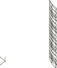
Plots produced by these analyses are shown in Figure 1 and Figure 2. Figure 1 is obtained from the eigenvalue buckling analysis and shows the original (cylindrical) mesh and the critical buckling mode. Figure 2 is generated when the load level has reached a local maximum (increment 8) in the Riks analysis using the perturbed mesh.
![]()
Input files
- fpert001.inp
-
Eigenvalue buckling analysis.
- fpert002.inp
-
Riks analysis using a perturbed mesh.
- fpert.f
-
Postprocessing program.
![]()
Figures