Analysis of a rotating fan using substructures and cyclic symmetry | ||
| ||
ProductsAbaqus/Standard
Geometry and material
The structure is a fan consisting of a central hub and four blades, as shown in Figure 1. The blades and the hub are made up of S4R shell elements. The material is elastic, with a Young's modulus of 200 GPa and a Poisson's ratio of 0.29. The density of the material is 7850 kg/m3. All nodes along the mounting hole in the hub are fixed.
![]()
Models
Four different models are considered, as follows:
The fan is modeled as a single structure (no substructures).
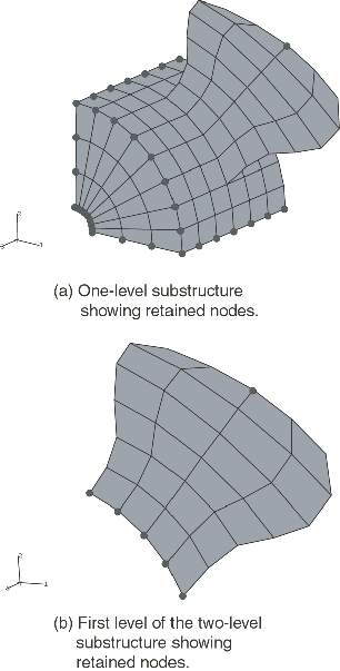
One quadrant of the fan, consisting of a quarter of the hub and a single blade, is reduced to a substructure. The fan is then modeled with four substructures (a single-level substructure). During substructure generation all degrees of freedom are retained for the nodes along the edges of the hub in each quadrant as well as one node at the blade tip (see Figure 2).
A single fan blade is reduced to a substructure, which is then combined with one-quarter of the hub to form a higher level substructure. Four of these substructures are then combined to form the fan (similar to the single-level substructure), thus forming a multi-level substructure. Nodes along the base of the fan blade and one node at the tip of the blade have all their degrees of freedom retained during generation of the fan blade substructure as shown in Figure 2. At the higher level substructure generation stage, nodes along the edge of the hub in each quadrant as well as the node at the blade tip have their degrees of freedom retained.
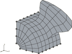
One quadrant of the fan, consisting of a quarter of the hub and a single blade, is modeled with and without substructures as a datum sector for the cyclic symmetry analysis technique. Two surfaces, which are at 90° to each other, are chosen to serve as the slave and master surfaces for the cyclic symmetry surface-based tie constraint. The finite element mesh contains matching nodes on the symmetry surfaces; therefore, both surfaces are defined with lists of nodes or node set labels. The axis of cyclic symmetry is parallel to the global z-axis and passes through the point on the x–y plane with coordinates (3.0, 3.0). The cyclic symmetry model is shown in Figure 3. The entire model consists of four repetitive sectors.
Both a frequency analysis and a static analysis are performed on the first three models. Static analysis followed by a frequency extraction and a modal-based steady-state dynamic analysis are performed for the cyclic symmetry model. Stress- and load-stiffening effects due to the centrifugal loading on the fan are built into the substructure stiffness during generation using a preload step with large-displacement formulation. To get the proper stress stiffening in the hub of the multi-level substructure, the centrifugal load defined in the lowest-level substructure (the blade) needs to be captured with a substructure load case and must be applied as a substructure load in the next-level substructure.
To improve the representation of the substructure's dynamic behavior in the global analysis, m dynamic modes, which are extracted using an eigenfrequency extraction step, are included during the substructure generation using eigenmode selection. The reduced mass matrix obtained with the default value of corresponds to the Guyan reduction technique, while corresponds to the restrained mode addition technique. In the “Results and discussion” section below the solution obtained for the model without substructures (the “full model”) is used as the reference solution.
For the cyclic symmetry model without substructures the eigenvalue extraction procedure is performed on the preloaded structure. The nonlinear static step has the centrifugal load applied to the blade. Eigenvalues are requested using the Lanczos eigenvalue solver, which is the only eigensolver that can be used for an eigenfrequency analysis with the cyclic symmetry analysis technique. The specification of cyclic symmetry modes in an eigenvalue analysis is demonstrated in one problem. This makes it possible to extract only the eigenmodes that have the requested cyclic symmetry. When this option is omitted, the eigenvalues are extracted for all possible (three) cyclic symmetry modes. In the discussion that follows the solution obtained for the cyclic symmetry model is compared to the solution for the entire 360° model (the reference solution). An eigenvalue analysis without the preload step is performed for the cyclic symmetry model with substructures. Twenty eigenvalues are extracted and compared to the reference solution obtained for the entire 360° model with substructures. The third step in the cyclic symmetry model problems is a frequency-domain, modal-based, steady-state procedure. It calculates the response to pressure loads projected on a specific cyclic symmetry mode.
![]()
Results and discussion
Results for the frequency analysis and the static analysis appear below.
Frequency analysis for models with substructures
Frequencies corresponding to the 15 lowest eigenvalues are extracted and tabulated in Table 1 for each model. To study the effect of retaining dynamic modes during substructure generation, the substructure models are run after extracting 0, 5, and 20 dynamic modes during substructure generation.
While the Guyan reduction technique (0) yields frequencies that are reasonable compared to those of the full model, the values obtained with 5 retained modes are much closer to full model predictions, especially for the higher eigenvalues. Increasing the number of retained modes to 20 does not yield a significant improvement in the results, consistent with the fact that in the Guyan reduction technique the choice of retained degrees of freedom affects accuracy, while for the restrained mode addition technique the modes corresponding to the lowest frequencies are by definition optimal.
When substructures are used in an eigenfrequency analysis, it is to be expected that the lowest eigenfrequency in the substructure model is higher than the lowest eigenfrequency in the corresponding model without substructures. This is indeed the case for the single-level substructure analysis, but for the multi-level substructure analysis the lowest eigenfrequency is below the one for the full model. This occurs because the stress and load stiffness for the lowest-level substructure (the blade) are generated with the root of the blade fixed, whereas in the full model the root of the blade will move radially due to the deformation of the hub under the applied centrifugal load. Hence, the substructure stiffness is somewhat inaccurate. Since the radial displacements at the blade root are small compared to the overall dimensions of the model (of order 10−3), the resulting error should be small, as is observed from the results.
Table 2 shows what happens if the NLGEOM parameter is omitted during the preloading steps. It is clear that the results are significantly different from the ones that take the effect of the preload on the stiffness into account. In this case the lowest eigenfrequency in the substructure models is indeed above the lowest eigenfrequency in the model without substructures.
Static analysis for models with substructures
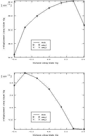
A static analysis of the fan is carried out about the preloaded base state by applying a pressure load of 105 Pa normal to the blades of the fan. The axial displacement of the outer edge of the fan blade due to the pressure load is monitored at nodes along path , as shown in Figure 1. The results are shown in Figure 4; there is good agreement between the solutions for the substructure models and the full model.
While substructures can be generated from models that exhibit nonlinear response, it must be noted that, once created, a substructure always exhibits linear response at the usage level. Hence, a preloaded substructure will produce a response equivalent to that of the response to a linear perturbation load on a preloaded full model. Consequently, the full model is analyzed by applying the centrifugal preload in a general step and the pressure load in a linear perturbation step. Since an analysis using substructures is equivalent to a perturbation step, the results obtained do not incorporate the preload deformation. Thus, if the total displacement of the structure is desired, the results of this perturbation step need to be added to the base state solution of the structure.
Steady-state analysis with preload for the cyclic symmetry model
A modal-based, steady-state analysis of the fan is carried out about the preloaded base state, as shown in fan_cyclicsymmodel_ss.inp. In the general static step, which includes nonlinear geometry, the centrifugal load is applied to the datum sector. Only symmetric loads can be applied in general static steps with the cyclic symmetry analysis technique. A sequence of three eigenvalue extraction and steady-state dynamics steps follows the preload step. Each eigenvalue extraction requests only one cyclic symmetry mode that is used in the load projection in the steady-state dynamic analysis that follows. The analysis specifies that modes belonging to the cyclic symmetry modes 0, 1, and 2 should be extracted. The computed eigenvalues are identical to those obtained for the entire 360° model, as shown in Table 1. The additional information obtained during the eigenvalue extraction is the cyclic symmetry mode number associated with each eigenvalue. In the case of 4 repetitive sectors, all the eigenvalues corresponding to cyclic symmetry mode 1 appear in pairs; the eigenvalues corresponding to modes 0 and 2 are single. The lowest two eigenvalues correspond to cyclic symmetry mode 1, followed by the single eigenvalues corresponding to cyclic symmetry modes 2 and 0. For a comparison with the cyclic symmetry model option, the eigenvalue problem is also modeled with multi-point constraint type CYCLSYM (see fansubstr_mpc.inp). To verify the use of substructures with the cyclic symmetry model, it was determined that the eigenvalues obtained with fansubstr_cyclic.inp were identical to those obtained with fansubstr_1level_freq.inp. The last step is the modal-based, steady-state dynamic analysis. A pressure load is applied to the entire structure as projected onto three different cyclic symmetry modes.
![]()
Input files
- fan_cyclicsymmodel_ss.inp
Cyclic symmetry model with static, eigenvalue, and steady-state dynamics steps with the load projected onto the cyclic modes 0, 1, and 2, respectively.
- fansubstr_1level_freq.inp
Single-level substructure usage analysis with a frequency extraction step.
- fansubstr_1level_static.inp
Single-level substructure usage analysis with a static step.
- fansubstr_multi_freq.inp
Multi-level substructure usage analysis with a frequency extraction step.
- fansubstr_multi_static.inp
Multi-level substructure usage analysis with a static step.
- fansubstr_freq.inp
Frequency extraction without substructures.
- fansubstr_static.inp
Static analysis without substructures.
- fansubstr_mpc.inp
Single-level usage analysis demonstrating the use of cyclic symmetry MPCs.
- fansubstr_gen1.inp
Substructure generation for a single blade used in the multi-level substructure generation file fansubstr_gen2.inp.
- fansubstr_gen2.inp
Multi-level substructure generation used infansubstr_multi_freq.inp and fansubstr_multi_static.inp.
- fansubstr_gen3.inp
Single-level substructure generation used infansubstr_1level_freq.inp, fansubstr_1level_static.inp, and fansubstr_mpc.inp.
- fansubstr_cyclic.inp
Single-level substructure with the cyclic symmetry model used in a frequency analysis.
![]()
Tables
| Eigenvalue no. cycles/sec | With substructuring: 1 level | With substructuring: 2 levels | Full model | ||||
|---|---|---|---|---|---|---|---|
| m=0 | m=5 | m=20 | m=0 | m=5 | m=20 | ||
| 1 | 6.9477 | 6.7901 | 6.7891 | 6.7655 | 6.6269 | 6.6258 | 6.7890 |
| 2 | 6.9477 | 6.7901 | 6.7891 | 6.7655 | 6.6269 | 6.6258 | 6.7890 |
| 3 | 8.0100 | 7.7207 | 7.7198 | 7.8162 | 7.5563 | 7.5552 | 7.7198 |
| 4 | 8.2009 | 7.8816 | 7.8810 | 8.1986 | 7.8813 | 7.8807 | 7.8810 |
| 5 | 11.341 | 11.020 | 11.010 | 11.123 | 10.802 | 10.792 | 11.009 |
| 6 | 11.341 | 11.020 | 11.010 | 11.123 | 10.802 | 10.792 | 11.009 |
| 7 | 12.529 | 11.930 | 11.912 | 11.539 | 11.142 | 11.124 | 11.910 |
| 8 | 14.751 | 14.397 | 14.346 | 13.450 | 13.256 | 13.211 | 14.348 |
| 9 | 17.787 | 14.432 | 14.432 | 17.208 | 14.455 | 14.455 | 14.431 |
| 10 | 18.922 | 14.779 | 14.775 | 18.797 | 14.751 | 14.747 | 14.774 |
| 11 | 21.250 | 14.779 | 14.775 | 19.860 | 14.751 | 14.747 | 14.774 |
| 12 | 21.250 | 16.034 | 15.995 | 19.860 | 15.645 | 15.623 | 15.991 |
| 13 | 28.250 | 17.699 | 17.624 | 28.066 | 17.129 | 17.057 | 17.624 |
| 14 | 28.691 | 19.034 | 19.019 | 28.628 | 18.914 | 18.901 | 19.008 |
| 15 | 28.691 | 21.333 | 21.178 | 28.628 | 20.014 | 19.885 | 21.176 |
| Eigenvalue no. cycles/sec | With substructuring | Full model | |
|---|---|---|---|
| 1 level | 2 levels | ||
| 1 | 4.4795 | 4.4795 | 4.4795 |
| 2 | 4.4795 | 4.4795 | 4.4795 |
| 3 | 4.5511 | 4.5511 | 4.5511 |
| 4 | 4.8889 | 4.8889 | 4.8889 |
| 5 | 9.5431 | 9.5431 | 9.5426 |
| 6 | 9.5431 | 9.5431 | 9.5426 |
| 7 | 9.7921 | 9.7921 | 9.7918 |
| 8 | 12.632 | 12.633 | 12.632 |
| 9 | 14.005 | 14.005 | 14.005 |
| 10 | 14.336 | 14.336 | 14.336 |
| 11 | 14.336 | 14.336 | 14.336 |
| 12 | 15.489 | 15.489 | 15.489 |
| 13 | 16.861 | 16.861 | 16.860 |
| 14 | 18.241 | 18.241 | 18.232 |
| 15 | 19.036 | 19.036 | 19.034 |
![]()
Figures