ROTATION

Connection type ROTATION provides a rotational connection between two nodes where the relative rotation between the nodes is parameterized by the rotation vector. In two-dimensional and axisymmetric analyses, the ROTATION connection type involves a single (scalar) relative rotation component.

Although available components of relative motion exist for the ROTATION connection type in three-dimensional analysis, the finite rotation parameterization of the connection is not necessarily well-suited for defining connector behavior. If a finite, three-dimensional ROTATION connection with connector behavior is desired, either the CARDAN or EULER connection type typically is more appropriate.

When connection type ROTATION is used in a connector element connected to ground at the element's first node, the rotational components relative to the orientation at ground are identical to the Abaqus convention for nodal rotation degrees of freedom. Hence, connection type ROTATION can be used in conjunction with prescribed connector motion (see Connector actuation) to specify finite rotation boundary conditions in local coordinate directions using the Abaqus convention for finite rotation boundary conditions.

Related Topics
Connector elements
Connector element library
In Other Guides
*CONNECTOR BEHAVIOR
*CONNECTOR SECTION

ProductsAbaqus/StandardAbaqus/ExplicitAbaqus/CAE

Description

Figure 1. Connection type ROTATION.

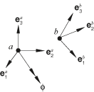
The rotation connection does not impose kinematic constraints. The rotation connection is a finite rotation connection where the local directions at node b are parameterized relative to the local directions at node a by the rotation vector. Let ϕ be the rotation vector that positions local directions {e1b,e2b,e3b} relative to {e1a,e2a,e3a}; that is,

eib=exp[ϕ^]eia

for all i=1,2,3, where ϕ^ is the skew-symmetric matrix with axial vector ϕ. See Rotation variables for a discussion of finite rotations.

The available components of relative motion in the ROTATION connection are the change in the rotation vector components positioning the local directions at node b relative to the local directions at node a. Therefore,

uri=ϕi-(ϕ0)i+2nπϕiϕ,

where ϕ0 is the initial rotation vector, n0 is an integer accounting for rotations with magnitude greater than 2π, all vector components are components relative to the local directions eia, and i=1,2,3. The connector constitutive rotations are

urimat=ϕi-θiref+2nπϕiϕ.

The kinetic moment in a rotation connection is

mi=mrotationeia,    i=1,2,3.

In two-dimensional and axisymmetric analyses ur1=ur2=0 and m1=m2=0.

Summary

ROTATION
Basic, assembled, or complex: Basic
Kinematic constraints: None
Constraint moment output: None
Available components: ur1,ur2,ur3
Kinetic moment output: m1,m2,m3
Orientation at a: Optional
Orientation at b: Optional
Connector stops: θiminϕiθimax
Constitutive reference angles: θiref
Predefined friction parameters: None
Contact force for predefined friction: None