PROJECTION FLEXION-TORSION | |||||||||
|
| ||||||||
ProductsAbaqus/StandardAbaqus/ExplicitAbaqus/CAE
Description
The PROJECTION FLEXION-TORSION connection does not impose kinematic constraints. The PROJECTION FLEXION-TORSION connection describes a finite rotation by three angles: flexion 1, flexion 2, and torsion (, , and ). However, the flexion 1, flexion 2, and torsion angles do not represent three successive rotations. The two component flexion angles ( and ) make up the total flexion angle between two shafts and measure the angle of misalignment of the two shafts. The torsion angle measures the twist of one shaft relative to the other.
The first shaft direction at node a is , and the second shaft direction at node b is . Let the two shafts form an angle , called the total flexion angle. Then,
The flexion angle is a rotation by about the (unit) rotation vector,
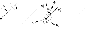
The PROJECTION FLEXION-TORSION connection is formulated in terms of the unit vector normal to a plane, , and two unit vectors spanning this plane, and . See Figure 1. The plane with normal vector is referred to as the flexion-torsion plane. The component flexion angles and are determined from and by projection onto the two in-plane directions:
The torsion angle in a PROJECTION FLEXION-TORSION connection can be understood from a finite successive rotation parameterization 3–2–3. In terms of the 3–2–3 parameterization the total flexion angle is the second successive rotation angle, and the torsion angle is the sum of the first and third successive rotation angles. The torsion angle between the two shafts is defined as
where positive torsion angles are rotations about the positive -direction and m is an integer.
The PROJECTION FLEXION-TORSION connection avoids the singularity that occurs in the sweep angle of the FLEXION-TORSION connection when the total flexion angle vanishes. As a result, the PROJECTION FLEXION-TORSION connection is better suited for defining bushing-like behavior for flexion response that varies with the direction of in the flexion-torsion plane.
The available components of relative motion , , and are the changes in the two flexion angles and the torsion angle and are defined as
where , , and are the initial flexion component angles and torsion angle, respectively. The connector constitutive rotations are
The kinetic moment in a PROJECTION FLEXION-TORSION connection is
![]()
Summary
| ||||||||||||||||||||||||||||