PLANAR | |||||||||
|
| ||||||||
ProductsAbaqus/StandardAbaqus/ExplicitAbaqus/CAE
Description
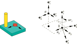
Connection type PLANAR imposes kinematic constraints and uses local orientation definitions equivalent to combining connection types SLIDE-PLANE and REVOLUTE.
![]()
Friction
Predefined Coulomb-like friction in the PLANAR connection relates the kinematic constraint forces and moments in the connector to the friction forces in the translations in the local 2–3 plane and the frictional moment in the rotation about the local 1-direction. These two frictional effects are discussed separately below.
The frictional effect due to sliding in the 2–3 plane is formally written as
where the potential represents the magnitude of the frictional tangential tractions in the connector in a direction tangent to the local 2–3 plane on which contact occurs, is the friction-producing normal force on the same plane, and is the friction coefficient. Frictional stick occurs if ; and sliding occurs if , in which case the friction force (CSFC) is .
The normal force is the sum of a magnitude measure of force-producing connector forces, , and a self-equilibrated internal contact force, :
The contact force magnitude is defined by summing the following two contributions:
a force contribution, (the constraint force enforcing the SLIDE-PLANE constraint); and
a force contribution from “bending,” , obtained by scaling the bending moment, (the magnitude of the constraint moments enforcing the REVOLUTE constraint), by a length factor, as follows:
where R represents a characteristic radius of the “puck” (as illustrated in Figure 2) in the local 2–3 plane. If R is 0.0, is ignored.
Figure 2. Illustration of the effective internal friction contact forces.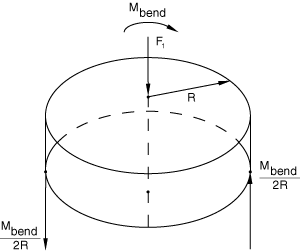
Thus,
where .
The magnitude of the frictional tangential moment, is computed using
Since the frictional effects due to rotation about the 1-direction are quantified, the frictional effect is formally written in terms of moments generated by tangential tractions and moments generated by contact forces as
where the potential represents the magnitude of the frictional tangential moment in the connector about the 1-direction, is the friction-producing normal moment about the same axis, and is the friction coefficient. Frictional stick in rotation occurs if ; and sliding occurs if , in which case the friction moment (CSM1) is .
The normal moment is the sum of a magnitude measure of friction-producing connector moments, , and a self-equilibrated internal contact moment, :
The contact moment magnitude is defined by summing the following two contributions:
a moment from a contact force in the 2–3 plane, (the constraint moment enforcing the SLIDE-PLANE constraint):
where , R represents a characteristic radius of the “puck” (as illustrated in Figure 2) in the local 2–3 plane (if R is 0.0, is ignored), and the 2/3 factor comes from integrating moment contributions from a uniform pressure () over the circular contact patch; and
a moment contribution from “bending,” (the magnitude of the constraint moments enforcing the REVOLUTE constraint):
Thus,
The magnitude of the frictional tangential tractions, is computed using
![]()
Summary
| ||||||||||||||||||||||||||||