HINGE | |||||||||
|
| ||||||||
ProductsAbaqus/StandardAbaqus/ExplicitAbaqus/CAE
Description
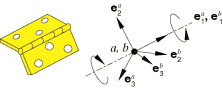
Connection type HINGE imposes kinematic constraints and uses local orientation definitions equivalent to combining connection types JOIN and REVOLUTE.
The connector constraint forces and moments reported as connector output depend strongly on the order and the location of the nodes in the connector element (see Connector behavior). Since the kinematic constraints are enforced at node b (the second node of the connector element), the reported forces and moments are the constraint forces and moments applied at node b to enforce the HINGE constraint. Thus, in most cases the connector output associated with a HINGE connection is best interpreted when node b is located at the center of the device enforcing the constraint. This choice is essential when moment-based friction is modeled in the connector since the contact forces are derived from the connector forces and moments, as illustrated below. Proper enforcement of the kinematic constraints is independent of the order or location of the nodes.
![]()
Friction
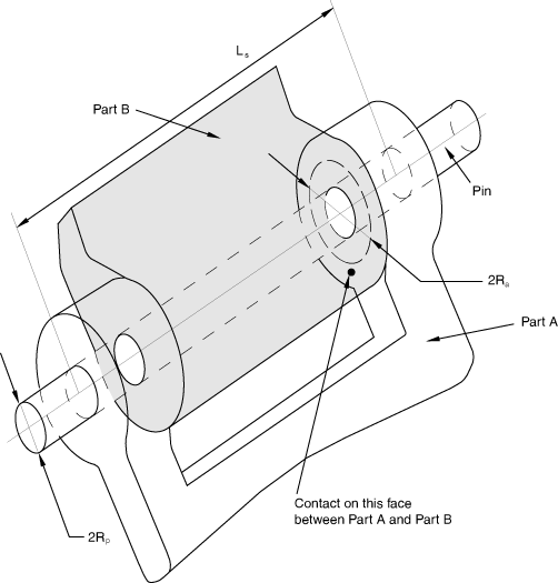
Predefined Coulomb-like friction in the HINGE connection relates the kinematic constraint forces and moments in the connector to a friction moment (CSM1) in the rotation about the hinge axis. The table below summarizes the parameters that are used to specify predefined friction in this connection type as discussed in detail next. A typical interpretation of the geometric scaling constants is illustrated in Figure 2.
Since the rotation about the 1-direction is the only possible relative motion in the connection, the frictional effect is formally written in terms of moments generated by tangential tractions and moments generated by contact forces, as follows:
where the potential represents the moment magnitude of the frictional tangential tractions in the connector in a direction tangent to the cylindrical surface on which contact occurs, is the friction-producing normal moment on the same cylindrical surface, and is the friction coefficient. Frictional stick occurs if ; and sliding occurs if , in which case the friction moment is .
The normal moment is the sum of a magnitude measure of friction-producing connector moments, , and a self-equilibrated internal contact moment (such as from a press-fit assembly), :
The magnitude measure of friction-producing connector contact moments, , is defined by summing the following contributions:
a moment from an axial force, , where and is an effective friction arm associated with the constraint force in the axial direction (the radius could be interpreted as an average radius of the outer sleeve cylindrical sections as found in a typical door hinge or as an effective radius associated with the hinge end caps, if they exist; if is 0.0, is ignored); and
a moment from normal forces to the cylindrical face, , where is the radius of the pin cross-section in the local 2–3 plane and is itself a sum of the following two contributions:
a radial force contribution, (the magnitude of the constraint forces enforcing the translation constraints in the local 2–3 plane):
a force contribution from “bending,” , obtained by scaling the bending moment, (the magnitude of the constraint moments enforcing the REVOLUTE constraint), by a length factor, as follows:
where represents a characteristic overlapping length between the pin and the sleeve. If is 0.0, is ignored.
Thus,
where .
The moment magnitude of the frictional tangential tractions, .
![]()
Summary
| ||||||||||||||||||||||||