FLEXION-TORSION | |||||||||
|
| ||||||||
ProductsAbaqus/StandardAbaqus/ExplicitAbaqus/CAE
Description
The FLEXION-TORSION connection does not impose kinematic constraints. The FLEXION-TORSION connection describes a finite rotation by three angles: flexion, torsion, and sweep (, , and ). However, the flexion, torsion, and sweep angles do not represent three successive rotations. The flexion angle between two shafts measures the angle of misalignment of the two shafts and is always reported as a positive angle. The torsion angle measures the twist of one shaft relative to the other.
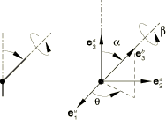
The sweep angle orients the rotation vector, in the – plane, for the flexion motion. See Figure 1. Since the flexion angle is never negative, the sweep angle may undergo discontinuous jumps by up to radians when the flexion angle passes through zero. An analysis may give inaccurate results or may not converge if any jump occurs in the sweep angle. In general, the sweep angle is not used as an available component of relative motion for which connector behavior is defined. Rather, it is used to define angular dependence for the elastic constitutive response in flexion deformations (as an independent component in the connector elastic behavior definition). Since the sweep angle is restricted to the interval to radians, any dependence on the sweep angle should be periodic, such that the behavior for is the same as . Since is a singular point for which the sweep angle is not uniquely defined, it is strongly recommended that any connector behavior that defines flexural moment versus flexion angle gives zero moment at zero flexion angle. If connector behavior is defined in the sweep available component, the sweep moment must be zero at flexion angles and .
The FLEXION-TORSION connection is similar to a finite successive rotation parameterization 3–2–3. However, in terms of the 3–2–3 parameterization, the sweep angle is the first rotation angle, the flexion angle is the second rotation angle, and the torsion angle is the sum of the first and third rotation angles.
The first shaft direction at node a is , and the second shaft direction at node b is . Let the two shafts form an angle , called the flexion angle. Then,
The flexion angle is a rotation by about the (unit) rotation vector
The torsion angle between the two shafts is defined as
where positive torsion angles are rotations about the positive -direction, and m is an integer.
The sweep angle measures the angle from to the projection of onto the – plane. With this definition
It follows that the flexion rotation vector, , can be written
A singularity in the definition of the sweep angles occurs when the flexion angle vanishes. In this case ; that is, the torsion and sweep angle axes are coincident, and the two angles are no longer independent. When , the sweep angle is assumed zero, .
The available components of relative motion , , and are the changes in the flexion, torsion, and sweep angles and are defined as
where and are the initial flexion and torsion angles, respectively. The initial value of the sweep angle is chosen to be zero if the shafts align initially. The connector constitutive rotations are
The kinetic moment in a FLEXION-TORSION connection is determined from the three component relationships:
![]()
Summary
| ||||||||||||||||||||||||||||