Offset faces | ||||||
|
| |||||
Context:
You can use target faces to compute an offset distance as shown in Figure 1, or you can specify an offset distance.
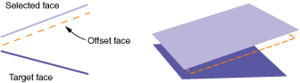
Regardless of the offset distance method that you choose, Abaqus/CAE creates all new faces at a constant offset distance from the selected faces, as shown in the figure. However, if you use target faces to compute the offset distance, Abaqus/CAE uses the selected faces and the target faces to calculate the thickness and offset distance at each node in the offset faces such that the behavior of the offset faces approximates the behavior of the original sections. You can view the result of these calculations after the part is meshed by showing the native mesh and toggling on Render shell thickness with a Scale factor of 1 in the Part Display Options dialog box.
You can review and edit the shell thickness values with the Assign thickness and Offset tool (for more information, see Assigning thicknesses and offsets), or you can specify a thickness for the new faces when you assign a section to them.
From the main menu bar, select .
Abaqus/CAE displays the Geometry Edit dialog box.
Tip: You can also offset faces using the  tool, located with the edit tools in the Part module toolbox. For a diagram of the edit tools in the toolbox, see Editing techniques.
Choose one of the available options to determine the offset distance:
Note:
Regardless of the calculation method, Abaqus/CAE applies a constant offset to the faces as shown in Figure 1. You must use another method to create new faces centered between converging or diverging faces.
- Use target faces to compute distance
Select a target face or faces. Abaqus/CAE computes the distance between the faces to be offset and the target faces by sampling the faces at several points. Use one of the following distance options:
-
Select Half the average distance to offset the new faces by this amount.
-
Select Fraction distance to closest point on face, and enter a value.
Abaqus/CAE offsets the new faces by the distance to the closest point on the target faces times the entered value.
-
Select Fraction distance to farthest point on face, and enter a value.
Abaqus/CAE offsets the new faces by the distance to the farthest point on the target faces times the entered value.
You can select the target faces using the same methods you used in Step 3. If your original faces are part of the reference representation for a midsurface model, you can click Auto Select to have Abaqus/CAE select appropriate faces from the opposite side of the reference representation. Varying distances between potential target faces may result in selections that only partially match the original faces. If necessary, click to modify the selections in the viewport.
-
- Distance
Enter an offset distance, or select
 to measure and enter a distance between objects in the viewport.
Negative values for the fraction or actual distance create an offset in the face normal direction; positive values create an offset in the opposite direction. If you are uncertain of the normal directions, use the Shell element normals general query to view the normal directions for shells in the model. For more information, see Obtaining general information about the model. The normals for solids point toward the outside, so a positive offset will create a face inside the part unless the offset distance is greater than the part thickness.
To exit the offset procedure, either
-
click the cancel button
 in the prompt area, or
 -
click mouse button 2 anywhere in the Abaqus/CAE window, or
-
select another operation from the Geometry Edit toolset or from the tools in the Part module.
-