Obtaining mesh information | |||||
|
| ||||
From the main menu bar, select .
Tip: You can also select the  tool in the Query toolbar.
 Abaqus/CAE displays the Query dialog box.
From the Query dialog box, select one of the following queries:
- Shell element normals
Abaqus/CAE displays the part or the assembly using the shaded render style. The side of the shell where the surface normal coincides with the shell normal (top face) is shaded brown; the opposite side (bottom face) is shaded purple.
- Beam element tangents
Abaqus/CAE displays cyan arrows indicating the direction of the beam tangents.
- Mesh stack orientation
For hexahedral and wedge elements, Abaqus/CAE colors the top face brown and the bottom face purple. Similarly, arrows indicate the orientation of quadrilateral elements. In addition, Abaqus/CAE highlights any element faces and edges that have inconsistent orientation.
- Mesh
For an assembly, part or part instance, geometric region, or element, Abaqus/CAE displays the following:
-
The total number of nodes and elements in the selected area
-
The number of elements for each element shape
By default, Abaqus/CAE displays mesh information in the message area, but you can display this information in a tabular format in the Mesh Statistics dialog box by toggling on Display detailed report in the prompt area. The Mesh Statistics dialog box also enables you to display mesh information by part instance or by element type.
-
- Element
Select an element. Abaqus/CAE displays the following in the message area:
-
The element label
-
The element topology
-
The element type that Abaqus/CAE will use for the analysis
-
Nodal connectivity
-
- Mesh gaps/intersections
Select a part instance. Abaqus/CAE highlights any edges of boundary faces of the model in the current viewport with the following:
-
Incompatible interfaces
-
Cracks or gaps
-
Intersections with other faces
In addition, if intersecting elements are found, Abaqus/CAE displays a dialog box that allows you to save a set containing elements that share the highlighted edges. If the model geometry is available, you can save a set containing the cells, faces, or edges related to the highlighted element edges.
-
- Free/Non-manifold edges
If the current viewport contains an assembly with more than one part instance, select one or more solid or shell instances for the query. Abaqus/CAE highlights two types of exterior element edges:
-
Free element edges are exterior edges that belong to a single exterior element face.
-
Non-manifold element edges are exterior edges shared by more than two adjacent exterior element faces.
If Abaqus/CAE finds free or non-manifold element edges, it displays the combined total number of these edges in the message area. Abaqus/CAE also displays a dialog box from which you can save an element set containing all the elements with the highlighted edges. If there are no free or non-manifold edges, the message area indicates that all exterior element edges are shared by exactly two exterior element faces. Figure 1 shows an extruded shell part with the free and non-manifold edges highlighted in red. The element edges along outer boundaries of the three planar faces are free edges. The element edges at the intersection of the three faces are non-manifold edges—each shared by three exterior element faces.
Figure 1. Free element edges make up the exterior edges, and non-manifold edges form the center where the three planar shells are joined.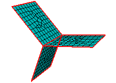
Shell parts should contain free edges and non-manifold edges where appropriate for the part design. Solid parts should not contain any free or non-manifold edges.
-
- Unmeshed regions
Abaqus/CAE displays a warning dialog and highlights any regions of the model that are not meshed. Toggle on Save regions in a set and select a set name to save a set containing the unmeshed regions.
If there are no unmeshed regions, Abaqus/CAE displays a message in the message area indicating that all regions are fully meshed. The query does not consider regions that do not require a mesh, such as display bodies and analytical rigid surfaces.
- Unassociated geometry
Abaqus/CAE displays the Query Unassociated Geometry dialog box, which enables you to highlight the cells, faces, edges, or vertices in your part or model that are not associated with a mesh. Toggle on Create set and select a set name to save a set containing the geometry that is not associated with a mesh.
If all the geometry you select is associated with a mesh, Abaqus/CAE displays a dialog box indicating that all selected geometry is associated with a mesh. The query does not consider regions that do not require a mesh, such as display bodies and analytical rigid surfaces.