Partitioning the unmeshable region and meshing the top-down regions | ||
| ||
Context:
The file is included with the Abaqus installation, and you can use the following utility to obtain a copy:
abaqus fetch job=bottomup_mesh_example_part.sat
For more information about ACIS files, see Importing parts from an ACIS-format file.
Figure 1 shows the original part. There are three solid regions; the regions colored green and yellow can be meshed using the top-down structured and swept meshing techniques, respectively, and the orange region is unmeshable with the automated top-down techniques and hexahedral elements.

To mesh the part, we will first create three partitions. The first two partitions create another top-down swept meshable region near the outer edge of the unmeshable region. The third partition is a face partition that you will use later as a vector for the bottom-up extrude method. You could apply bottom-up meshing techniques to the entire unmeshable region without partitioning. However, the resulting mesh would contain some poorly formed elements near the outer edge. In practice, you may create several bottom-up meshes before you make a satisfactory mesh for the entire region. Especially for more complex parts, you may want to save copies of a part with different meshing approaches until you decide which approach yields the best mesh.
Rotate the part so that you are viewing the bottom of the part, as shown in Figure 2.
Figure 2. Creating an offset partition on the bottom face.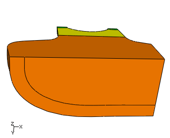
Complete the following steps to partition the face:
-
From the partition face tools in the module toolbox, select the
sketch method tool
 .
.
-
Select the bottom face of the part, and select one of the straight
edges to be vertical and on the right.
Abaqus/CAE opens the Sketcher.
-
From the
Sketcher
toolbox, select the offset tool
 .
.
- Select the curved edge, and click mouse button 2 to accept the selected edge.
-
Enter 2.5 in the prompt area as the
offset distance.
Abaqus/CAE displays a preview of the offset partition.
- Click if the offset is shown correctly (toward the interior of the part), or click if the offset is shown outside the part.
- Click mouse button 2 or click in the prompt area to partition the face.
Abaqus/CAE returns to the Mesh module and displays the partitioned face as shown in Figure 2.
-
From the partition face tools in the module toolbox, select the
sketch method tool
Extrude the face partition through the region.
-
From the partition cell tools in the module toolbox, select the
extrude/sweep method tool
 .
.
- Select the face partition created in Step 1 as the edge to extrude.
-
Click in the prompt
area, and pick the edge shown in
Figure 3.
Figure 3. Extruding the face partition through the cell.

- Click if the extrusion direction is shown correctly (through the region), or click to change the direction.
-
Click to partition the
cell.
Abaqus/CAE displays the outer region of the part in yellow, indicating that it can now be meshed using top-down swept meshing.
-
From the partition cell tools in the module toolbox, select the
extrude/sweep method tool
Partition the front face of the unmeshable region as shown in Figure 4.
Figure 4. Creating face partitions.
-
From the partition face tools in the module toolbox, select the
sketch method tool
.
-
Select the front face of the unmeshable region, and select an edge
to be vertical and on the right.
Abaqus/CAE opens the Sketcher.
-
Use the vertical construction line tool
 to create a construction line as shown in
Figure 5.
Figure 5. Using a vertical construction line to partition the face.
to create a construction line as shown in
Figure 5.
Figure 5. Using a vertical construction line to partition the face.
-
Use the connected lines tool
 to create a line connecting the two points where the
vertical construction line intersects the face of the part.
to create a line connecting the two points where the
vertical construction line intersects the face of the part.
- Create a second line connecting the upper point of the vertical line to the point where the fillet ends on the front face—the line should be nearly horizontal.
- Click mouse button 2 or click in the prompt area to partition the face.
There are now three regions in the part that you can mesh using the top-down meshing techniques.
-
From the partition face tools in the module toolbox, select the
sketch method tool
