Continuing the bottom-up mesh

There are at least three methods that you can use to complete the mesh for the part. The simplest method would be to create another swept mesh, using the bottom of the mesh that you just completed and the two faces extending out from the fillet on the top of the remaining unmeshed area as the source side, the three geometric vertical faces and the set of vertical element faces as the connecting sides, and the unmeshed portion of the bottom face as the target side. This method would complete the part mesh in a single bottom-up meshing step, and the elements would be fully associated with the selected faces. You could also use the bottom-up extrude method with the bottom face of the part as the extrude distance. However, for demonstration purposes we will use a longer process that combines use of the bottom-up extrude method, the associativity tool, and the Edit Mesh toolset.

This task shows you how to:

Creating a bottom-up extruded mesh:

  1. Select the Extrude method, and click Select to the right of Source side.

  2. Select the element faces at the bottom of the previous bottom-up mesh, as shown in Figure 1, as the source side for the second bottom-up mesh.

    Figure 1. Selecting element faces as the source side.

  3. Click Done in the prompt area to accept the selected faces.

    The Create Bottom-Up Mesh dialog box reappears.

  4. Click the Select button to choose a vector for the extruded mesh.

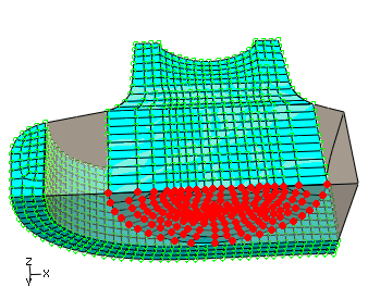
  5. Select the upper endpoint of the partition as the starting point of the vector, and select the lower endpoint as the end of the vector. Figure 2 shows the extrusion vector.

    Figure 2. Selecting the vector for the bottom-up extruded mesh.

  6. Enter 10 for the Number of layers.

    There are 10 elements on the inner face of the top-down swept mesh. Using the same number of elements for the extruded mesh will provide a better match when you create the third, and final, bottom-up mesh.

  7. Verify that the extrude depth is set using the default Use vector length method, and click Mesh in the Create Bottom-Up Mesh dialog box to create the mesh.

    Figure 3. The bottom-up extruded mesh.

Extending the extruded mesh:

Context:

The extruded bottom-up mesh ends near the bottom face of the region, as dictated by the nonplanar source side and the length of the extrusion vector. You can edit the nodes in the last extruded element layer so that they end exactly on the bottom face of the region.

  1. Select the Edit Mesh toolset , located at the bottom of the Mesh module toolbox.

  2. Select the Node category, and click on Project in the Edit Mesh dialog box.

  3. Use the angle method to select all the nodes on the bottom of the bottom-up extruded mesh, as shown in Figure 4; and then click Done in the prompt area.

    Figure 4. Selecting the nodes to project.

  4. Select the bottom face of the bottom-up region, and click Yes in the prompt area to project the nodes onto the face.