Checking the association of the bottom-up mesh with the geometry | ||
| ||
Context:
In most cases if you select a geometric feature, such as a face, to define the bottom-up mesh, Abaqus/CAE automatically associates the appropriate elements with that face. However, in cases where the geometry is not used, such as the extruded bottom-up mesh in the center of the example part, the elements are associated only with the region, not the nearby face where a load might be applied. (For more information, see Mesh-geometry association.) The following procedure associates the elements on the bottom and front faces of the part with the geometric faces:
Select the bottom face of the bottom-up region, as shown in Figure 1.
The elements created in the final bottom-up meshing step are colored yellow because they were already associated when the face was used as the target side of the final bottom-up swept mesh. However, the elements in the semi-circular extruded mesh are not associated with the face.
Figure 1. Existing mesh associations on the bottom face.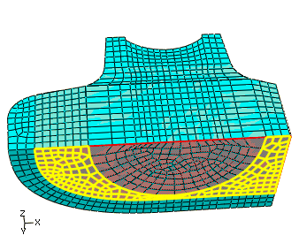
Use the angle method to select all the faces on the bottom of the bottom-up region. When you are finished, all of the element faces on the bottom of the bottom-up region should be colored yellow, as shown in Figure 2.
Figure 2. Final mesh associations on the bottom face.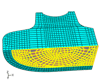
Note:
If you did not remove the outer top-down meshed cell, use of the angle method would have selected the top-down element faces for association as well as the bottom-up faces, leading to an error message when you attempted to associate the faces.