Applying a mesh stack orientation | ||||
|
| |||
Context:
The stack orientation tool allows you to assign a stack orientation to all cells or to selected cells within a solid part or part instance, as long as the cells do not have tetrahedral elements assigned. You can use the tool to apply a stack orientation quickly to a group of cells in a single operation. You assign the stack orientation based on a selected face; the stack is oriented such that the selected face is the top of the stack. Abaqus/CAE applies the orientation regardless of the mesh technique used for the cells; so the sweep direction, if one exists, does not matter.
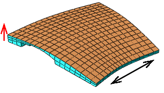
The stack orientation tool was used to assign an orientation through the thickness of the part in Figure 1, as shown by the red arrow; the top faces of the elements are colored brown. The complex profile of the swept solid part did not allow the desired stack orientation using the sweep path—the two available sweep directions are indicated by the black arrow in the figure.
Application of a new stack orientation may vary depending on the cells selected. Figure 2 illustrates a case where the stack direction changes as more cells are meshed. The upper left face was used for the reference orientation, so the mesh orientations for the two disconnected cells in the center image match this orientation. However, when the center cell is meshed, the orientation of the elements in the lower right cell is updated to align with the other two cells, as shown in the image on the right.

From the main menu bar, select .
Abaqus/CAE displays prompts in the prompt area to guide you through the procedure.
Tip: You can also set a mesh stack direction using the  tool, located in the Mesh module toolbox (for more information, see Using the Mesh module toolbox.), and the button, located in the Mesh Controls dialog box.